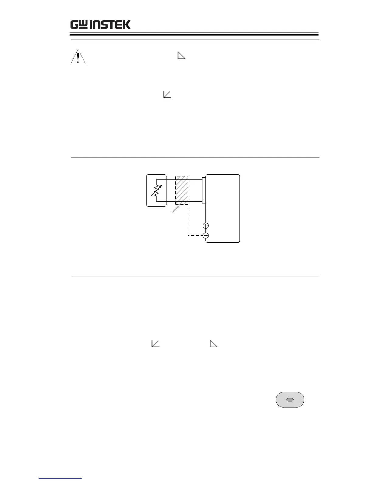
EasyManuals Logo

GW Instek PSW Series User Manual

GW Instek PSW Series
184 pages
To Next Page IconTo Next Page
To Previous Page IconTo Previous Page
Page #125 background imageLoading...
Page #125 background image
ANALOG CONTROL
125
Note
The Ext-R
configuration is recommended for
safety reasons. In the event that the cables become
accidentally disconnected, the voltage output will
drop to zero. Under similar circumstances using
Ext-R , an unexpected high voltage would be
output.
If switches are used to switch between fixed
resistances, use switches that avoid creating open
circuits. Use short-circuit or continuous resistance
switches.
Connection
PSWEXT-R
Analog
connector
7
6
Output
Terminal
2 core shielded
wire or twisted
pair
Pin6 EXT-R
Pin7 EXT-R
Wire shield → negative (-) output terminal
Steps
1. Connect the external resistance according to the
connection diagrams above.
2. Set the F-90 (CV Control)
configuration settings to 2 for Ext-
R
or 3 for Ext-R .
Page 114
Be sure to cycle the power after the power
on configuration has been set.
3. Press the Function key and confirm
the new configuration settings (F-
90=2 or 3).
Function

Table of Contents

Other manuals for GW Instek PSW Series

Questions and Answers:

Question and Answer IconNeed help?

Do you have a question about the GW Instek PSW Series and is the answer not in the manual?

GW Instek PSW Series Specifications

General IconGeneral
Ripple & Noise (CC)≤ 3mArms
ProtectionsOVP, OCP, OTP
Remote SenseYes
ProgrammableYes
Operating Temperature0°C to 40°C
Storage Temperature-20°C to 70°C
Voltage Resolution1mV
Current Resolution1mA
Current Accuracy±0.1% + 10mA
Ripple & Noise (CV)≤1mVrms
Load Regulation (CC)≤0.1% + 5mA
Line Regulation (CC)≤0.1% + 5mA
Remote InterfaceUSB, RS232
DisplayLCD

Related product manuals