PSW Series User Manual
20
Standard 26 pin MIL connector
(OMRON XG4 IDC plug).
The analog control connector is
used to monitor current and voltage
output, machine status (OVP, OCP,
OTP etc.), and for analog control of
the current and voltage output.
Use an OMRON XG5 IDC socket as
the mating socket.
Output Terminals
(30, 80, 160 volt
models)
Positive (+) and negative (-) output
terminals.
Sense (-S) and Sense (+S) terminals.
Output Terminals
(250, 800 volt
models)
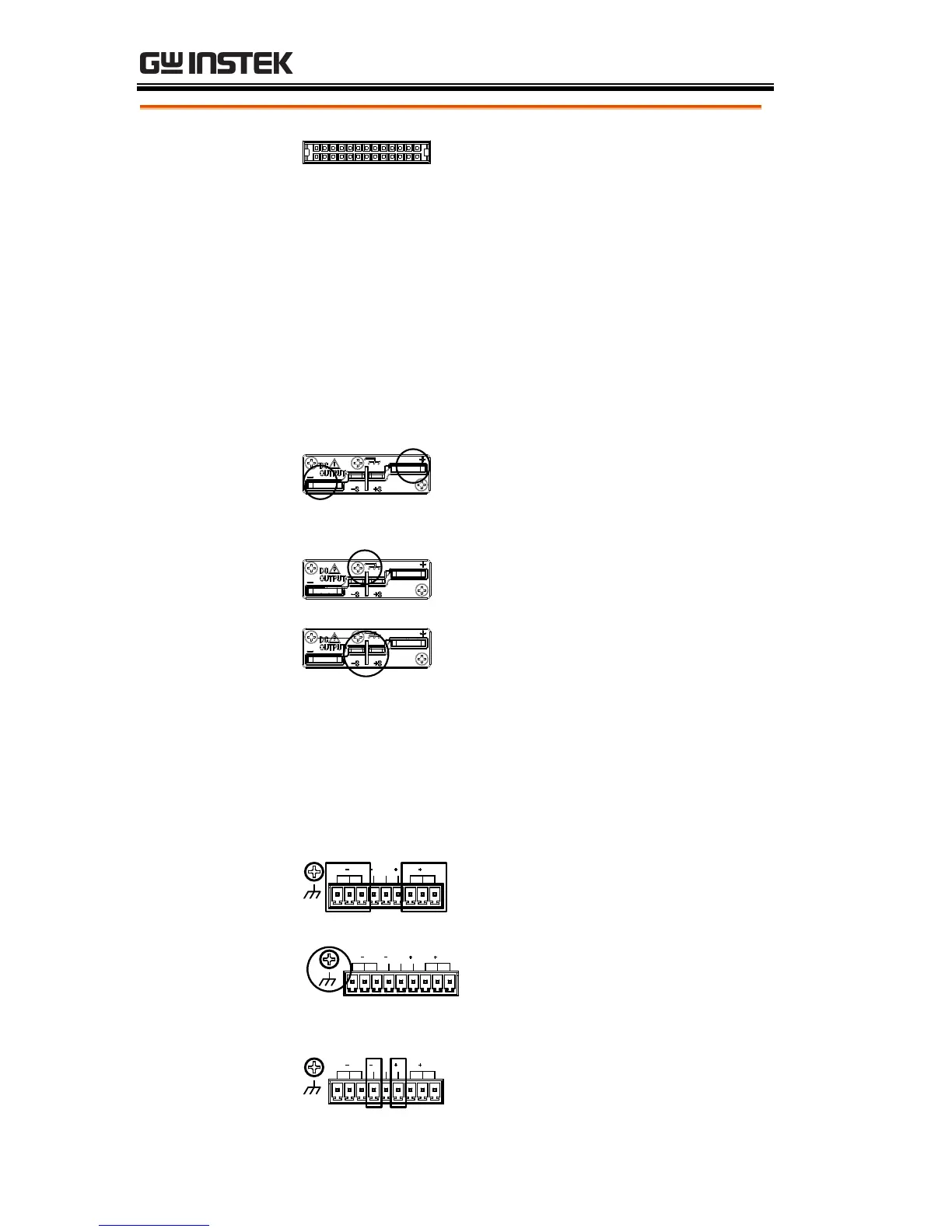
The 250 and 800 volt models use a 9 pin connector
and a plug for the output and sense terminal
connections. The plug is a MC420-38109Z plug by
DECA SwitchLab Inc. This plug is also available
separately (GW part number 39BT-50900401).
Positive (V+) and negative (V-)
output terminals (3 of each).
Sense (-S) and Sense (+S)
terminals.

 Loading...


