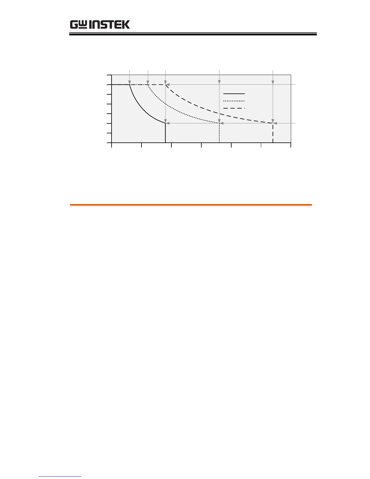
When the power supply is operating in
constant current mode (CC) a constant current
will be supplied to the load. When in constant
current mode the voltage output can vary,
whilst the current remains constant. When the
load resistance increases to the point where the
current limit (I
SET
) can no longer be sustained
the power supply switches to CV mode. The
point where the power supply switches modes
is the crossover point.
When the power supply is operating in CV
mode, a constant voltage will be supplied to
the load, whilst the current will vary as the
load varies. At the point that the load
resistance is too low to maintain a constant
voltage, the power supply will switch to CC
mode and maintain the set current limit.
The conditions that determine whether the
power supply operates in CC or CV mode
depends on the set current (I
SET
), the set voltage

 Loading...


