104
[DeviceC] mirroring-group 1 remote-probe vlan 2
[DeviceC] interface Ethernet 1/0/2
[DeviceC-Ethernet1/0/2] mirroring-group 1 monitor-port
[DeviceC-Ethernet1/0/2] undo stp enable
[DeviceC-Ethernet1/0/2] port access vlan 2
[DeviceC-Ethernet1/0/2] quit
4. Verify the configurations
After the configurations are completed, you can monitor all the packets received and sent by the
marketing department on the server.
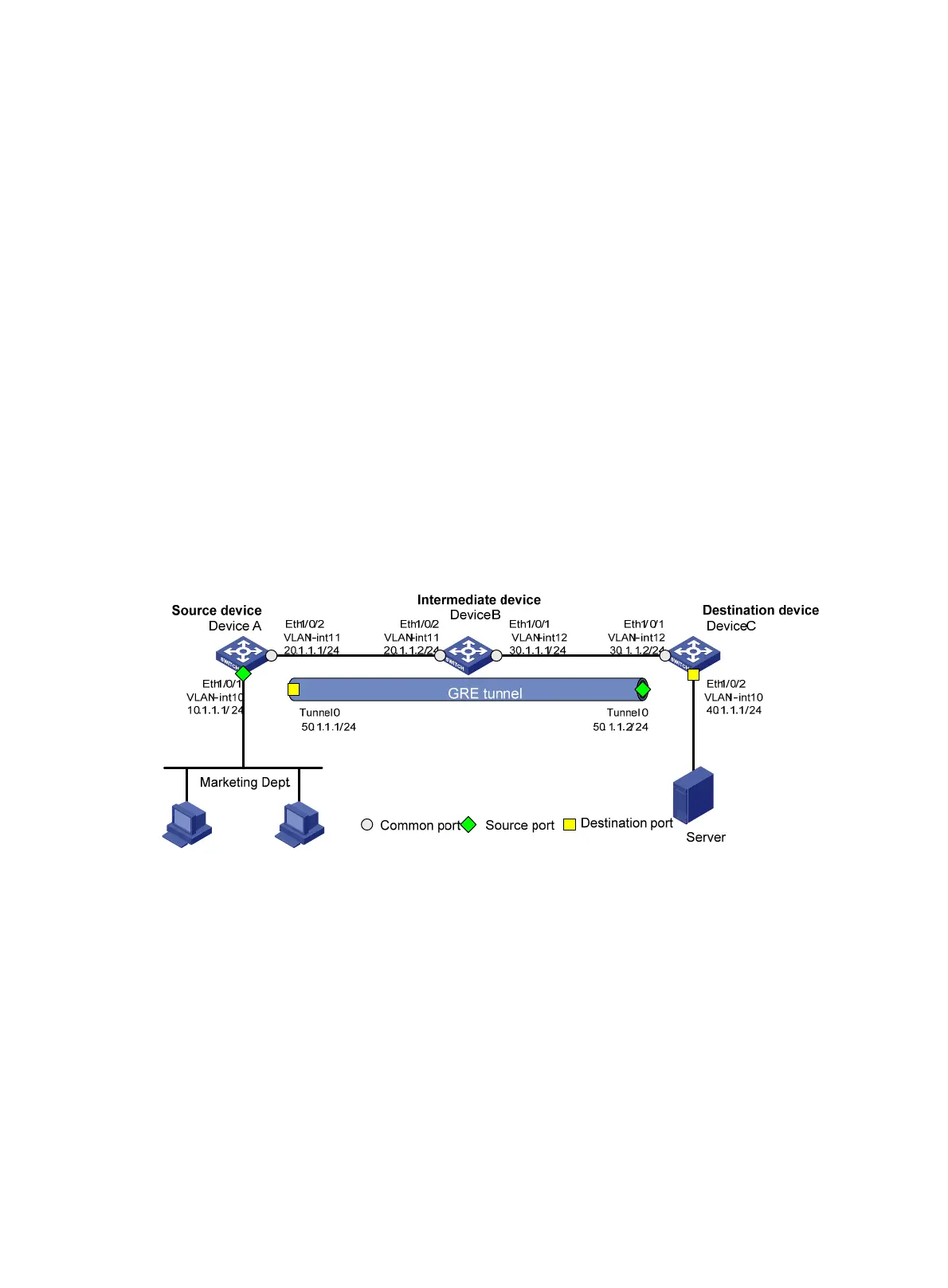
Layer 3 remote port mirroring configuration example
Network requirements
On the network shown in Figure 38:
• Device A connects to the marketing department through Ethernet 1/0/1 and connects to Ethernet
1/0/1 of Device B through Ethernet 1/0/2; Device C connects to the server through Ethernet
1/0/2 and connects to Ethernet 1/0/2 of Device B through Ethernet 1/0/1.
• Configure Layer 3 remote port mirroring to enable the server to monitor the bidirectional traffic of
the marketing department through a GRE tunnel.
Figure 38 Network diagram
Configuration procedure
1. Configure IP addresses for the tunnel interfaces and related ports on the devices.
Configure a VLAN, add interfaces to the VLAN, and configure IP addresses and subnet masks for related
ports and the tunnel interfaces according to the configurations shown in Figure 38.
2. Configure Device A (the source device)
# Create tunnel interface Tunnel 0, and configure an IP address and subnet mask for it.
<DeviceA> system-view
[DeviceA] interface tunnel 0
[DeviceA-Tunnel0] ip address 50.1.1.1 24
# Configure Tunnel 0 to operate in GRE mode, and configure source and destination IP addresses for it.
[DeviceA-Tunnel0] tunnel-protocol gre
[DeviceA-Tunnel0] source 20.1.1.1