• Avoid excessive movement. Transport static-sensitive components in anti-static containers or
packages.
• Wear a wrist strap connected by a wire to earth ground.
• Work in a static-safe area with anti-static floor pads and work bench pads.
4.5 Wiring overview
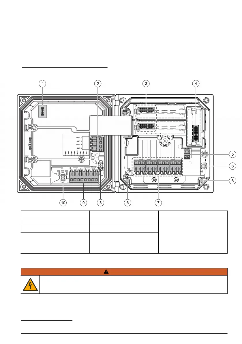
Figure 7 shows an overview of the wiring connections inside the controller with the high voltage
barrier removed. The left side of the figure shows the back side of the controller cover.
Note: Remove connector caps from the connectors before module installation.
Figure 7 Wiring connections overview
1 Service cable connection 5 AC and DC power connector
3
9 Discrete input wiring connector
3
2 4-20 mA output
3
6 Ground terminals 10 Digital sensor connector
3
3 Sensor module connector 7 Relay connections
3
4 Communication module
connector (e.g., Modbus,
Profibus, HART, optional
4-20 mA module, etc.)
8 Digital sensor connector
3
4.6 Wiring for power
W A R N I N G
Potential Electrocution Hazard. Always disconnect power to the instrument when making electrical
connections.
3
Terminals can be removed for improved access.
English 13

 Loading...


