1. Open the controller cover.
2. Feed the wires through the cable gland.
3. Adjust the wire as necessary and tighten the cable gland.
4. The jumpers are positioned immediately behind the connector. Remove the connector for
improved access to the jumpers and configure the jumper settings according to the type of input
as shown in Figure 10.
5. Close the controller cover and tighten the cover screws.
6. Configure inputs in the controller.
Note: In switch input mode the controller supplies 12 volts to the switch and is not isolated from the controller. In
voltage input mode the inputs are isolated from the controller (user input voltage from 0 to 30 volts).
4.11 Connect a digital sc sensor
Note: To connect an analog sensor, refer to the instructions supplied in the module or sensor manual.
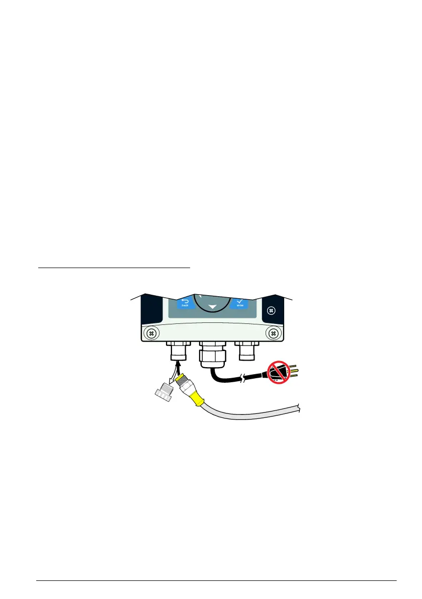
A digital sc sensor can be connected to the controller using the keyed quick-connect fitting (
Figure 11). A digital sensor can be connected with the controller powered on or off.
When a sensor is connected with the controller powered on, the controller does not automatically
perform a device scan. To make the controller perform a device scan, navigate to the
Test/Maintenance menu and select Scan Devices. If a new device is found, the controller performs
the installation process without further user action.
When a sensor is connected with the controller powered off, the controller will perform a device scan
when it is powered on again. If a new device is found, the controller performs the installation process
without further user action.
Retain the connector cap to seal the connector opening in case the sensor must be removed.
Figure 11 Digital sensor quick connect
4.12 Connect the optional digital communication output
The manufacturer supports Modbus RS485, Modbus RS232, Profibus DPV1 and HART
communication protocols. The optional digital output module is installed in the location indicated by
item 4 in Figure 7 on page 13. Refer to the instructions supplied with the network module for more
details.
For information about Modbus registers, go to http://www.de.hach.com or http://www.hach.com and
search Modbus registers or go to any sc200 product page.
4.13 Install a Secure Digital (SD) memory card
For instructions on how to install an SD card in the controller, refer to Figure 12. Information on how
to use the SD memory card can be found in the expanded version of this manual.
To remove an SD card, push down on the edge of the card and release, then pull the card up and out
of the slot. After the card is removed, close the slot cover and tighten the cover screws.
English
21

 Loading...


