3. Move the equipment away from the device receiving the interference.
4. Reposition the receiving antenna for the device receiving the interference.
5. Try combinations of the above.
3.2 Product overview
The controller displays sensor measurements and other data, can transmit analog and digital signals,
and can interact with and control other devices through outputs and relays. Outputs, relays, sensors
and sensor modules are configured and calibrated through the user interface on the front of the
controller.
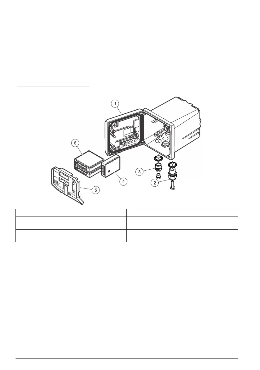
Figure 1 shows the product components. Components may vary according to controller configuration.
Contact the manufacturer if parts are damaged or missing.
Figure 1 System components
1 Controller 4 Network module (optional)
2 Strain relief assembly (optional depending on
controller version)
5 High-voltage barrier
3 Digital connection fitting (optional depending on
controller version)
6 Sensor modules (optional)
3.2.1 Sensors and sensor modules
The controller accepts up to a maximum of two sensor modules or two digital sensors (depending on
the controller configuration), along with one communication module. A single digital sensor and a
single sensor module can be installed in combination. A variety of sensors can be wired to the sensor
modules. Sensor wiring information is given in the specific sensor manuals and in the user
instructions for specific modules.
3.2.2 Relays outputs and signals
The controller has four configurable relay switches and two analog outputs. An optional analog
output module can increase the number of analog outputs to five.
3.2.3 Device scans
With two exceptions, the controller automatically scans for connected devices without user input
when it is powered on. The first exception is when the controller is powered on for the first time
before initial use. The second exception is after the controller configuration settings have been set to
their default values and the controller is powered on. In both cases, the controller first displays the
language, date and time edit screens. After the language, date and time entries are accepted, the
controller performs a device scan. Refer to Connect a digital sc sensor on page 21 for instructions
about how to scan for devices when the controller is already powered on.
6
English

 Loading...


