85
7000056136-0
EN
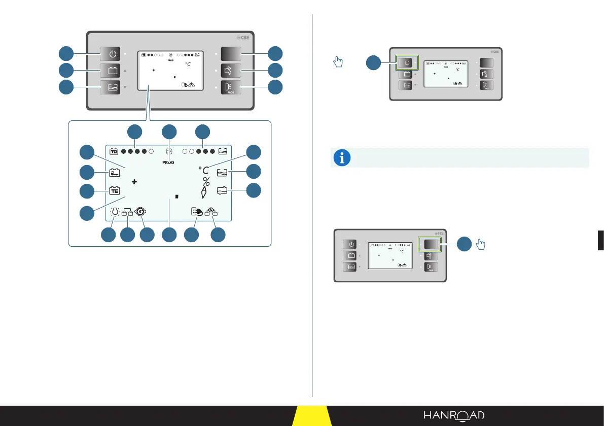
General layout of the interface
12V
PC210
5
25
ext.
T
8
88
ext.
T
int.
T
1
2
3
4
5
6
7 13
1418 19 20 21 22
8
9
11
12
10
15
16
17
On/o button
This button switches the instrumentation and control panel on and o.
12V
PC210
5
25
ext.
T
1
>2s
1 On/o button
■ Press the on/o button (1) for two seconds to switch the instrumentation
and control panel on.
On start-up, the display unit performs an operating test by
displaying all the symbols (including the unused symbols).
■ Press the on/o button (1) for two seconds again to switch the
instrumentation and control panel o.
Power button for the lights, refrigerator, and electrical sockets
This button switches on the lights, refrigerator, and electrical sockets.
12V
PC210
5
25
ext.
T
1
1 Power button for the lights, refrigerator, and sockets
■ Press the control button for the lights, refrigerator, and sockets to switch on:
– The lighting inside the cabin.
– The refrigerator.
– The electrical sockets.
1 On/o button
2 Battery voltage monitoring button
3 Fresh water tank ll monitoring button
4 Control button for the lights, refrigerator,
and electrical sockets
5 Water pump control button
6 User programming button
7 Cabin battery charge level
8 Fresh water tank level
9 Engine battery
10 Cabin battery
11 Outside temperature
12 Inside temperature
13 User programming menu
14 Measurement
15 Unit of measurement
16 Fresh water tank empty
17 Waste water tank full
18 Minimum voltage device
19 Parallel battery activation with engine
started
20 Engine on
21 Connection to 230 VAC system
22 Activation of engine battery charging
system