2-6 Installing the HN4000 Chassis in the Rack
HN4000 Hardware Installation Guide 920550-5020 Rev 14
b. Securetheextenderbrackettothe19”ANSIbracketwithtwooftheprovided
#12‐24rackscrewsand#12external‐toothlockwashers.
c. Repeatfortheright‐sidebracket,againbeingsurethattheextenderbracket’s
offsetistowardthefrontoftheHN4000asshowninthefigure.
Step
4. SlidetheHN4000intotherackandorientthemountingbracketholestoholesinthe
rack.
End of Procedure
2.5 Installing the HN4000Chassis in the Rack
Step 1. Locatethemounting‐holepositionsoneachsideoftherackthatwillbeusedfor
mountingtheHN4000chassis.
Step 2. EnsurethattheHN4000chassiswillbelevelusingtheselectedholes.Identifythe
mountingholeswithamarkingpenortape.
Step 3. LifttheHN4000chassisintoplace
intherackandalignthebracketmountingholes
withtherackmountingholes.
Step 4. Insertamountingscrewwithexternaltoothwasherintoeachofthefourbracket
holesandtightenthemwitha#2Phillipsscrewdriverto41‐48in‐lbs(4.6‐5.4Nm).
End of Procedure
2.6 Installing the Ground and Power Cables
Power Warning ‐This device contains connectors for two power sources. Disconnect all power
sources before servicing.
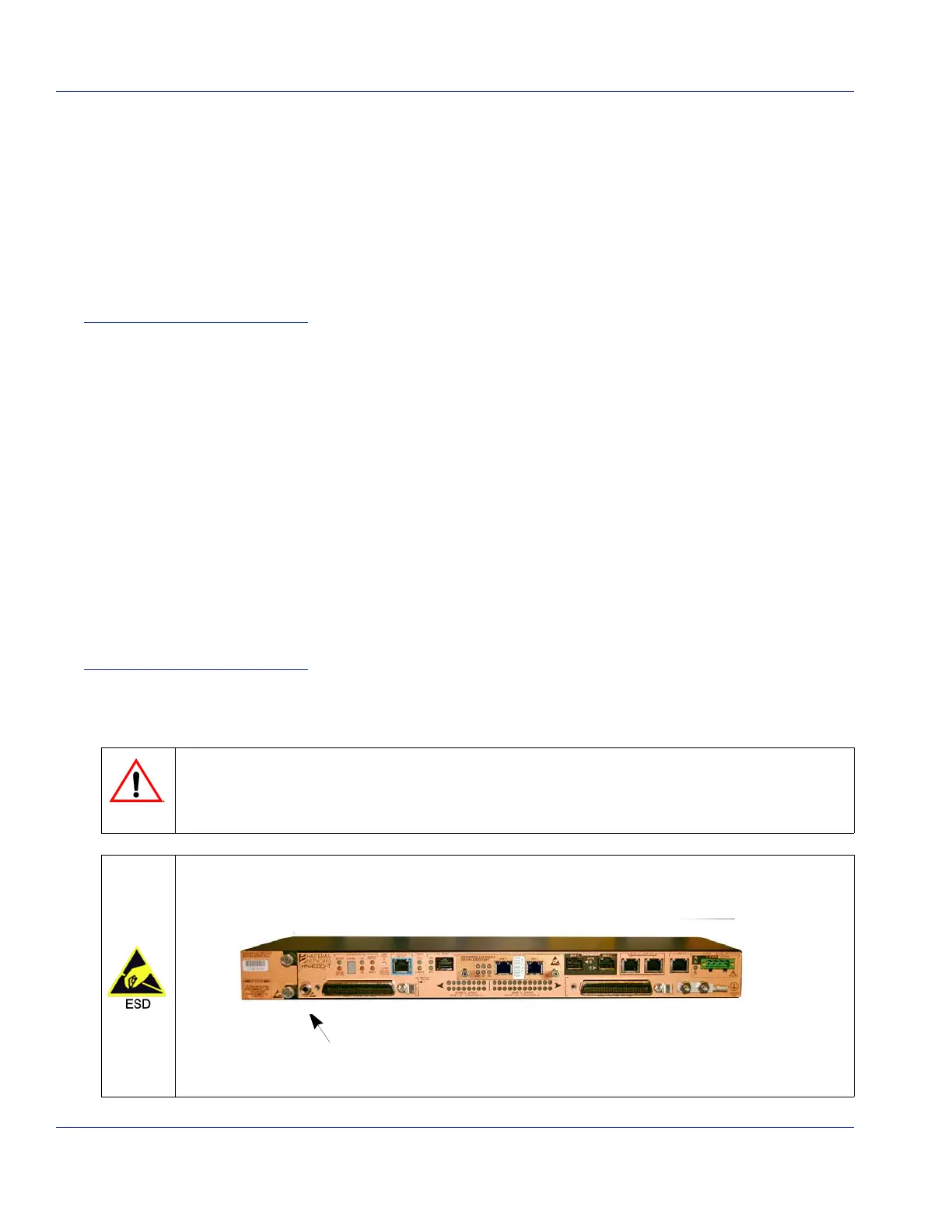
Follow ESD procedures per local practice. Always use a wrist strap attached to the ESD ground
jack located on the lower left side of the HN4000 chassis (
Figure 2‐6).
Figure 2-6 ESD Jack Location
 Loading...