Cabling the Alarm Port 4-15
920550-5020 Rev 14 HN4000 Hardware Installation Guide
4.6 Cabling the Alarm Port
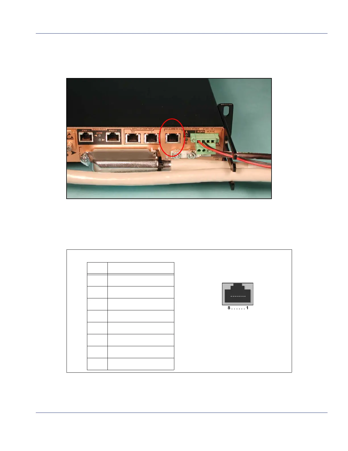
TheHN4000AlarmI/Oport(Figure 4‐10)isanRJ‐45connectorthatprovidesaninterfacefor
alarmsthattheswitchgeneratesaswellassupportinganinputforexternalalarms.
Figure 4-11 Alarm Port
AlarmsgeneratedbytheHN4000areavailableontheAlarmport’snormally‐openandnor‐
mally‐closedrelaycontacts.Table4‐5liststhesignalsthataresupportedbythealarmportand
theassociatedfigureshowsthepinlocationsintheport’sfemalejack(facingtheHN4000front
panel).
An
alarmcable(CBL100‐0010‐11)isavailableasanoptionfromHatterasNetworks.
This10ft.(3m)cableisterminatedononeendwithanRJ‐45connectorandunterminatedon
theotherend.
Table 4-5 Alarm I/O Port Pin Outs
Pin # Signal
1CriticalCommon
2CriticalNormallyOpen
3CriticalNormallyClosed
4MajorCommon
5MajorNormallyClosed
6MajorNormallyOpen
7AlarmIn
8AlarmInReturn
RJ-45 Pins (Facing HN4000)
 Loading...