Installing the Ground and Power Cables 2-7
920550-5020 Rev 14 HN4000 Hardware Installation Guide
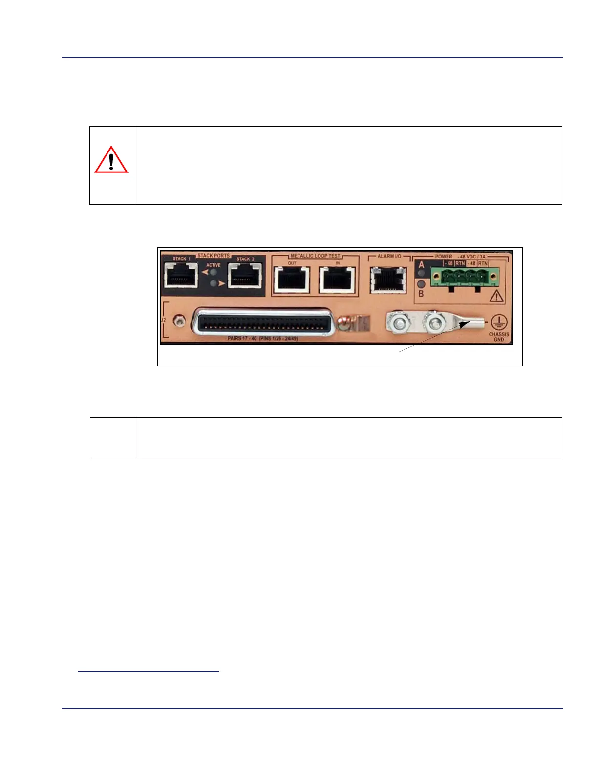
2.6.1 Connecting a Chassis Ground Cable
TakethefollowingstepstoconnectagroundcablefromtheHN4000chassistoanearth
ground.
Step 1. Measuretodeterminethelengthofgroundingcablerequiredtorunfromthechassis’
groundlug(Figure 2‐7)andagroundingpointontherack’sfuse/breakerpanel.
Figure 2-7 HN4000Ground Lug
Step 2. Cutalengthof10‐14AWG(2.6‐1.6mm)stranded/insulatedwiretothatlength.
Step 3. Removethetw o3/8inchhexnutsfromthegroundlug’sgroundingstudsandremove
thegroundlug.
Step 4. Striponeendofthecable(approximately3/8”(1.0cm))tofitintothe
groundlug.
Step 5. Usingacrimpingtool,crimptheHN4000groundlugtothecable.
Step 6. Replacethegroundlugontothe groundingstudsandfastenwiththetwo3/8inch
hexnuts.Tightenthehexnutsto20‐27in‐lbs(2.3‐3.0Nm).
Step 7. Dressthecablethrougha
cable‐guideslotinthechassis’right‐handbracket.
Step 8. Terminatetheunterminatedendofthegroundingcableincompliancewithlocal
practicesandfastenittothegroundingpointonthefuse/breakerpanel.
End of Procedure
The HN4000 must be permanently grounded to a Common Bonding Network (CBN).
Grounding of the HN4000 should be in compliance with local practices and must be to a protective
earth ground (clean, bare-metal).
The grounding connection must be made before copper-pair connections are made to the
device’s 2BASE-TL connectors.
Your local electrical code may require that a specific color (or colors) be used for the
protective-earth ground wire.
 Loading...