Cooling Unit Module Replacement 6-5
920550-5020 Rev 14 HN4000 Hardware Installation Guide
6.2 Cooling Unit Module Replacement
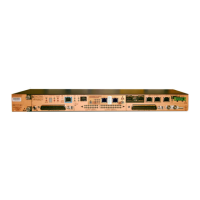
Figure 6‐3showstheHN4000switch’sFanCoolingUnitmoduleandtheCoolingUnitfailure
indicator.
Figure 6-3 Cooling Unit Module and Cooling Unit Failure Indicator
TheCoolingUnitmustbereplacediftheCoolingUnitfailureindicatoris“on.”Inaddition,
theCoolingUnitshouldberemovedatregularintervalstoinspectandclean(orreplace)
theunit’sfilter.
6.2.1 Removing the Cooling Unit Module
TakethefollowingstepstoremovetheCoolingUnitmodule.
Step 1. Readtheremovalprocedurestodetermineifthe2minutetimeintervalforhot‐
replacementcanbeaccomplished.Ifyouaregoingtoreplacethemodule’sfilterele‐
ment,haveareplacementelementavailable.
Step 2. Loosenthetwomountingscrews
thatsecurethemodule.
Removal and replacement of the Cooling Unit can be performed while the HN4000 is powered up,
without affecting data or management traffic. However, the replacement operation must be com-
pleted in two minutes or less to avoid over heating of the HN4000.
#1 Phillip’s screwdriver.
 Loading...