Lamp Test Button 3-5
920550-5020 Rev 14 HN4000 Hardware Installation Guide
3.3.2 Resetting the Alarm Port
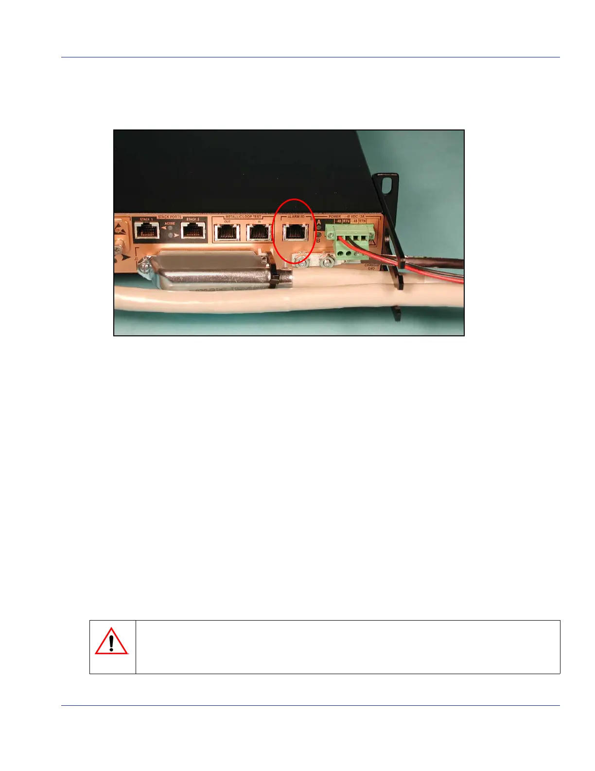
TheAlarmI/Oport(Figure 3‐5)isanRJ‐45connectorthatprovidesaninterfaceforalarmsthat
thedevicegeneratesaswellassupportinganinputforexternalalarms.
Figure 3-5 Alarm Port
AlarmsgeneratedbytheHN4000areavailableontheAlarmport’snormally‐openandnor‐
mally‐closedrelaycontacts.Seethesection”CablingtheAlarmPort” on page 4‐15fora
descriptionoftheAlarmport’spin‐outs.
PressingtheLAMPTESTbuttonformorethantwosecondsbutlessthanfiveseconds,
resets
thealarmport’srelaycontactstotheirdefaultsettings.
3.3.3 Changing the Switch ID Number
IfyoupressandholdtheLAMPTESTbuttononanHN4000forfivesecondsbutlessthanten
seconds,thedeviceentersswitch‐IDchangemode.Inthismode,theseven‐segmentchassis
LEDflashes.Then,eachtimethebuttonispressedandreleased,theswitchIDnumberis
incremented.
If,whileinswitch‐IDmode,thelamptestbuttonisnotpressedwithinfiveseconds,thedevice
exitsthemode.
IftheswitchIDischanged,thenewnumberisdisplayed,andthedeviceclearsthecurrentstar‐
tupconfigurationandreboots.
When the device is rebooted following a switch numbering change in switch-ID mode, any
system-startup information in the device’s startup configuration file will be lost and data and man-
agement traffic will be interrupted.
 Loading...