920550-5020 Rev 14 HN4000 Hardware Installation Guide
1
Troubleshooting
7
TheproceduresfortroubleshootingtheHN4000hardwareareprovidedinTable7‐1.Thesteps
withintheproceduresarelistedinthesuggestedorderthattheybeperformed.
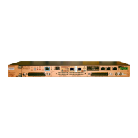
Figure 7-1 Device Connectors and LEDs
Table 7-1 HN4000 Troubleshooting Steps
Condition Solution
Allfront‐panelLEDsareoff. 1.Verifythatthedeviceisreceiving‐48VDCpower.
2.Verifythatthepowercableiswiredcorrectly(see”InstallingtheGround
andPowerCables” on page 2‐6).
3.Ifonlyonepowersourceisbeingused,switchthepowercablestothe
connectionthatisnotinuse(forexample,tothe“B”connectionifthe“A ”
connectionsarebeingused.
4.Replacethedevicewithaunitknowntobeinproperworkingcondition.
TheredSystemFAILLEDison. Innormaloperation,thesystemFAILLEDwillblinkonandoffimmediately
afterthe
deviceispoweredup(whilethedevicerunsitsself‐testdiagnostics).
IfthesystemFAILLEDisonafterdiagnosticshaverun,itindicatesthatthe
devicehasdetectedahardwareproblem.
1.Removepowerfromthedeviceandpoweritbackup.
2.Replacethedevicewithaunitknown
tobeinproperworkingcondition.
Field replaceable high-
speed network module
with dual-redundant ports
Modular, field
replaceable cooling
unit
Redundant
power
inputs
Subscriber ports - 40 pairs of
2BASE-TL and bonded 2BASE-TL
10/100
Management
Port
Main
chassis
Serial Craft
Port
System
Status LEDs
Stack
ports
MLT
ports
Alarm
port
Grounding
lug
 Loading...