920550-5020 Rev 14 HN4000 Hardware Installation Guide
1device
Front Panel Features
3
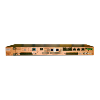
ThischapterdescribestheportsandLEDsthatarelocatedonthefrontpaneloftheHN4000
(Figure 3‐1).Refer toChapter 4forinformationaboutconnectorpin‐outassignments.
Figure 3-1 Device Ports and LEDs (HN4000e Shown)
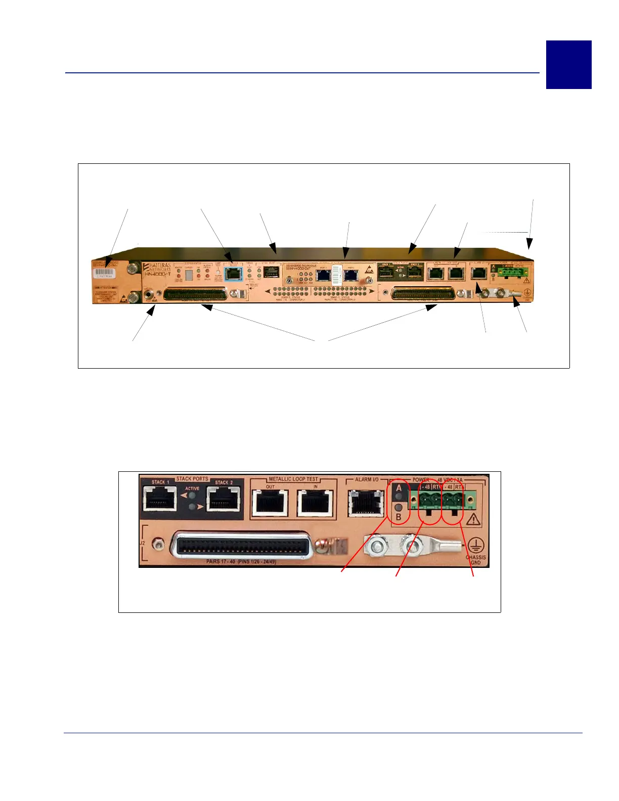
3.1 Power Connector and Power LEDs
Figure 3‐2showsadetailoftheHN4000device’spowerconnectorandpowerLEDs.
Figure 3-2 -48 VDC Power Connector
Universal I/O Slot for field
replaceable high-speed
network module with dual-
redundant ports
Modular, field
replaceable cooling
unit
Redundant
power inputs
Subscriber ports - 40 pairs of
2BASE-TL and bonded 2BASE-TL
10/100
Management
Port
Main chassis
Serial
Console
Port
Stack
Ports
MLT
Ports
Alarm
Port
Ground
Lug
-+
“B” Power
-+
“A” Power
Power
Source
LEDs
 Loading...