Cabling a Maintenance Terminal 4-13
920550-5020 Rev 14 HN4000 Hardware Installation Guide
4.5.1 HN4000e Model Console Port Pin Assignments
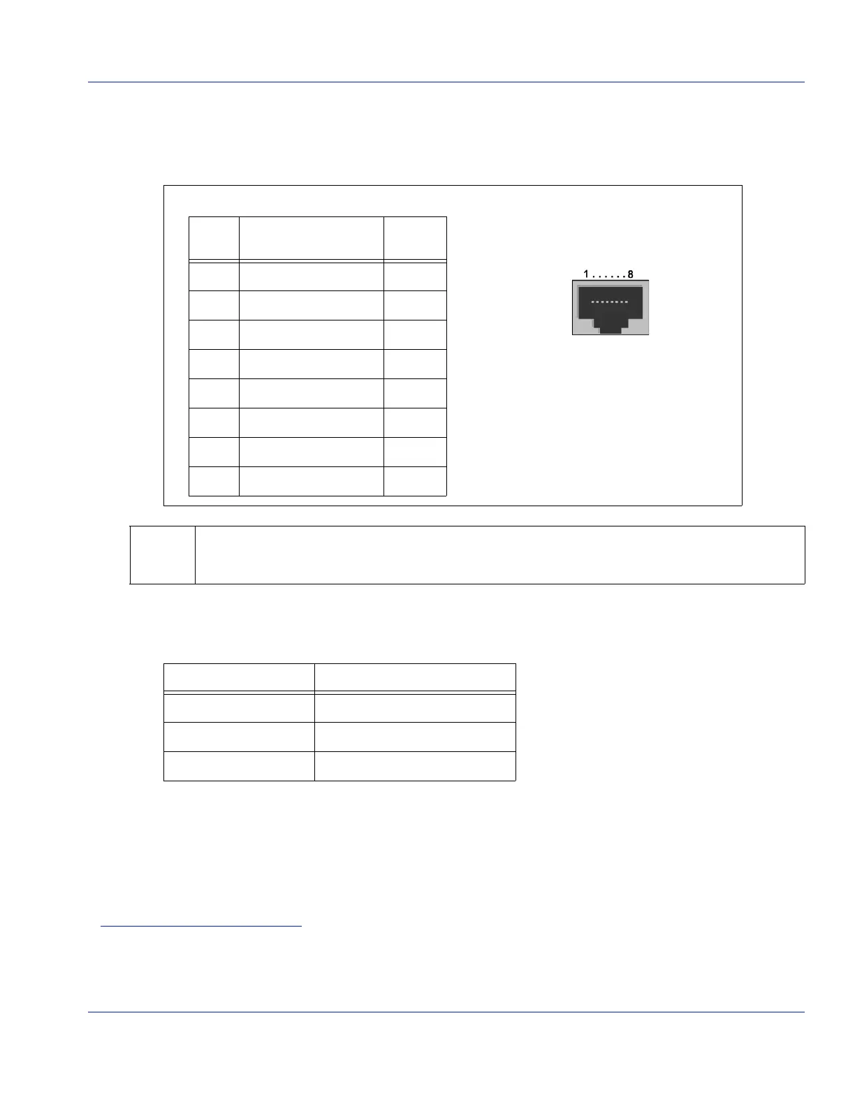
Table4‐5andFigure showsthepinassignmentsfortheHN4000eswitchmodel’sRJ‐45console
port.
1
AnoptionalRJ‐45toDB‐9adapterisavailablefromHatterasNetworks.Table4‐4showsthe
associationbetweentheRJ‐45andDB‐9pins.
1. ThefollowingCiscoSystemscablescanbeconnectedtotheRJ‐45consoleport:72‐3383‐01cableor72‐1259‐01cable
with74‐0495‐01adapter.Thesecablesareunshielded,andmustnotbeusedtopermanentlyinstallamaintenance
terminal.
The console-port connection is DCE, and the port will automatically detect whether the connection
is being made with a crossover or straight-through cable.
Table 4-4 RJ-45 to DB-9 Pin Association
HN400-U RJ-45 Pin # DB-9 Pin # (Female Connector)
3 (RxD) 2
5 (GND) 5
6 (TxD) 3
Table 4-3 Console Port Pin Outs
RJ-45
Pin #
Signal Device
I/O
1N/A N/A
2N/A N/A
3RxD(ReceiveData) Output
4 GND N/A
5 GND N/A
6TxD(TransmitData) Input
7N/A N/A
8N/A N/A
Figure 4-10 RJ-45 Pins for Console Port
(Facing HN4000e
)
HN4000e Console Port
 Loading...