3-2 Power Connector and Power LEDs
HN4000 Hardware Installation Guide 920550-5020 Rev 14
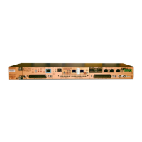
3.1.1 Power Connector
TheHN4000canbepoweredfromoneortw o‐48VDCpowersources.Iftwopowersources
areused,thedevicewillcontinuetooperatenormallyshouldoneofthesourcesfail.
Thepowerconnectorhasfourpins‐twopinsforeachofthetwo‐48VDCpowersourcesthat
can
beconnectedtothedevice.AsshowninFigure 3‐2onpage 3‐1,thepinsare(fromleftto
right):
❒ Pin1‐“A ” powersourcenegative(‐)connection
❒ Pin2‐“A ” powersourcepositive(+)connection
❒ Pin3‐“B”powersourcenegative(‐)connection
❒ Pin4‐“B”powersourcepositive(+)connection
3.1.2 Power Status LEDs
TherearetwopowerstatusLEDs:“A ” and“B.”
❒ “A ” LED‐On(steadygreen)when‐48VDCisdetectedatthe“A ” connections
(pins1and2)
❒ “B”LED‐On(steadygreen)when‐48VDCisdetectedatthe“B”connections
(pins3and4)
NotethatatleastoneofthepowerstatusLEDsmustbeonforthedevicetobeoperational.
BothpowerstatusLEDswillbeonwhentwooperationalpowersourcespowerareconnected.
 Loading...