109
8.4 Communication Methods
Standard Event Status Enable Register (SESER)
Setting any bit of the Standard Event Status Enable Register to 1
enables access to the corresponding bit of the Standard Event Status
Register.
Standard Event Status Register (SESR) and Standard Event Status
Enable Register (SESER)
Device-Specific Event Status Registers (ESR0 and ESR1)
This instrument provides two event status registers for controlling
events.
Each event register is an 8-bit register.
When any bit in one of these event status registers enabled by its
corresponding event status enable register is set to 1, the following
happens:
• For Event Status Register 0, bit 0 (ESB0) of the Status Byte Register
is set to 1.
• For Event Status Register 1, bit 1 (ESB1) of the Status Byte Register
is set to 1.
Event Status Registers 0 and 1 are cleared in the following situations:
• When a
*CLS command is executed
• When an Event Status Register query
(
:ESR0? or :ESR1?) is executed
• When the instrument is powered on
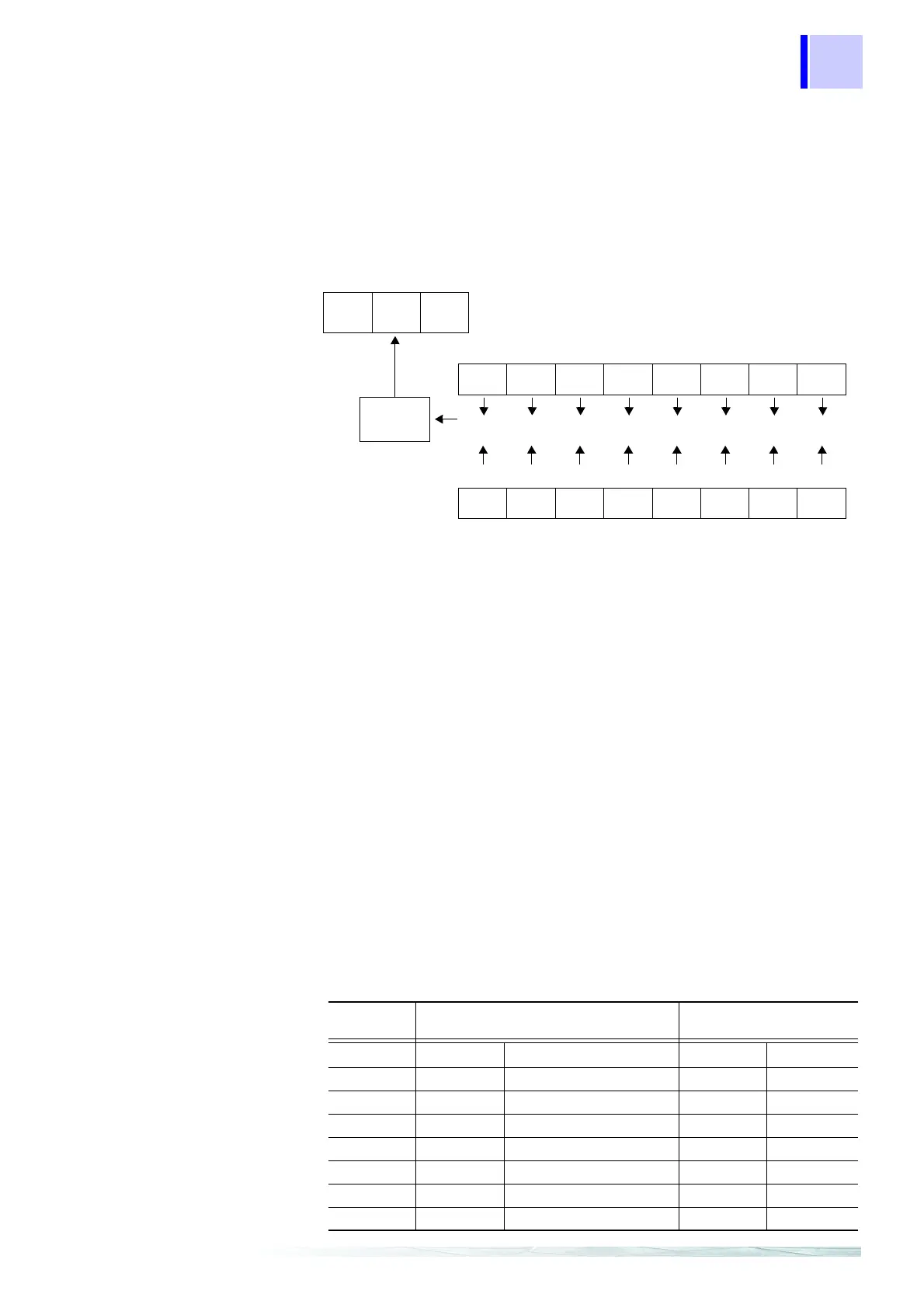
bit 7bit 6bit 5bit 4bit 3bit 2bit 1bit 0
PON URQ CME EXE DDE QYE RQC OPC
&&&&&&&&
bit 7bit 6bit 5bit 4bit 3bit 2bit 1bit 0
PON URQ CME EXE DDE QYE RQC OPC
Standard Event Status Register (SESR)
Standard Event Status Enable Register (SESER)
bit 6bit 5bit 4
SRQ
MSS
ESB MAV
Logical
sum
Event Status Register 0 (ESR0)
Event Status Register 1
(ESR1)
Bit 7
BIN1 BIN1 BIN9 BIN9
Bit 6 BIN0 BIN0 BIN8 BIN8
Bit 5 ERR Measurement Fault BIN7 BIN7
Bit 4 Hi High Comparator Result BIN6 BIN6
Bit 3 IN IN Comparator Result BIN5 BIN5
Bit 2 Lo Low Comparator Result BIN4 BIN4
Bit 1 INDEX End of Measurement BIN3 BIN3
Bit 0 EOC End of Conversion BIN2 BIN2