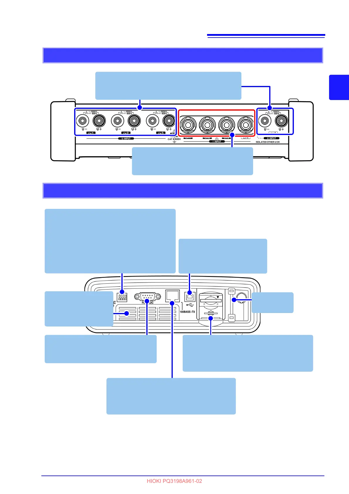
Right side
LAN interface
Connect a computer here using the optional
9642 LAN Cable.
See: (p.182)
RS-232C interface
Connect a GPS box using an RS-232C
cable.
External control terminal
IN : External input can be used as an event
trigger or as a recording start/stop signal.
OUT : Outputs a signal when an internal event
occurs.
GND : Serves as the ground terminal for the
external event input and output terminals.
See: (p.173)
Air vents
Do not block these
vents.
See: (p.7)
USB interface
Connect a computer here using
the included USB cable.
See: (p.178)
Strap eyelet
See: (p.40)
SD memory card slot
Insert an SD memory card here. Be sure to close
the cover when recording.
See: (p.43)
 Loading...


