11.1 Connecting Wires to the Pulse I/O Terminals
168
This section describes how to connect wires to the pulse I/O terminals. When using
pulse output, the signal must be pulled up to the external power supply.
See: 11.4, "Outputting a Pulse Signal" (p. 172)
Preparation items
11.1 Connecting Wires to the Pulse I/O Termi-
nals
To avoid electric shock or damage to the equipment, always
observe the following precautions when connecting to pulse
input and output terminals.
• Always turn off the power to the instrument and to any
device
s to be connected before making connections.
• Be careful to avoid exceeding the ratings of pulse
input and
output terminals.
• During operation, a wire becoming dislocated and contact-
ing anothe
r conductive object can be serious
hazard.
Secure the pulse input and output terminals.
• Ensure that devices and systems to be connected to the
pu
lse input and output terminals are properly isolated.
To avoid electric shock, use the recommended wire type to con-
nect to the current input terminals, or otherwise ensure that the
wire
used has sufficient current handling capacity and insulation.
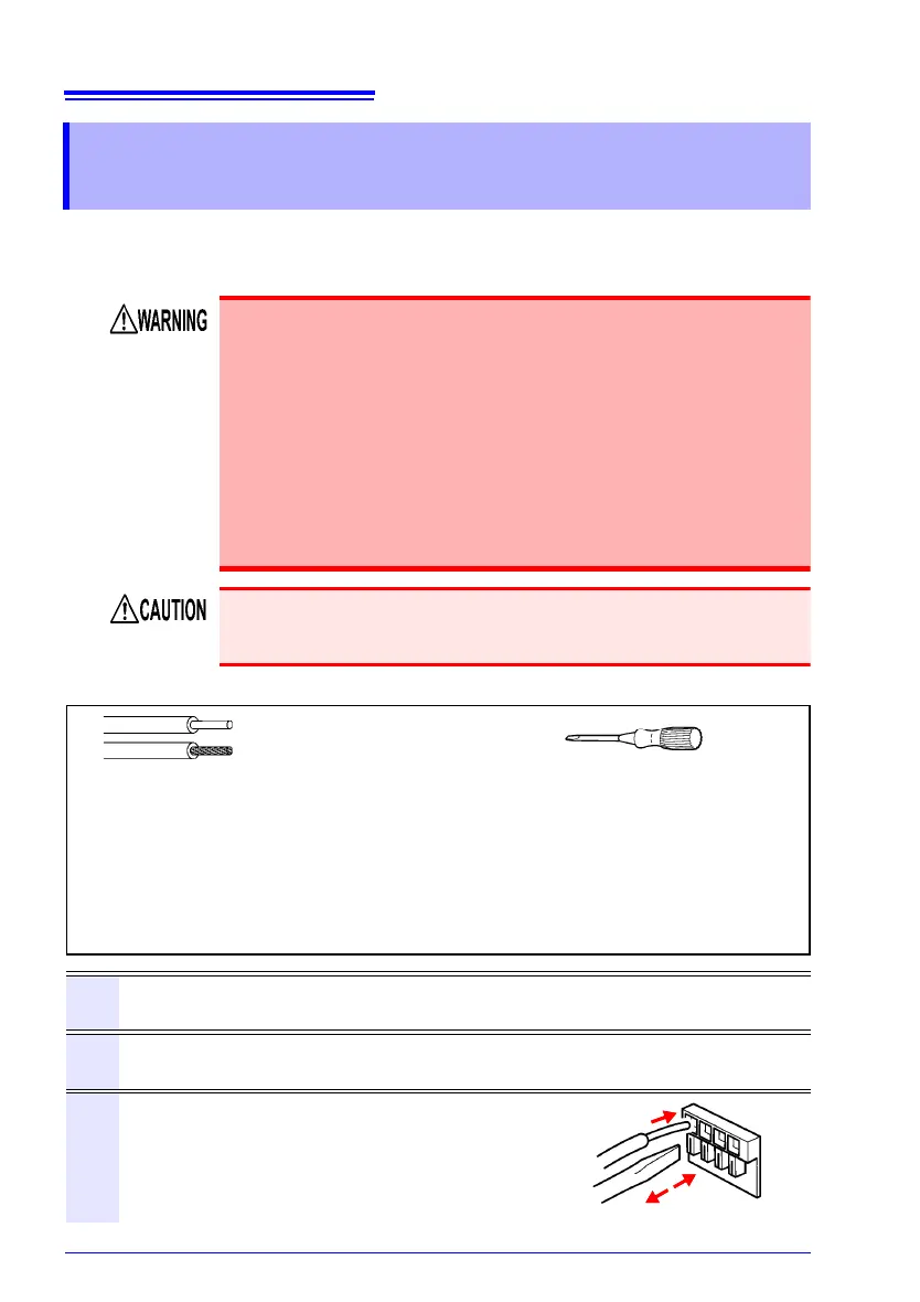
Electric wires that conform with:
single line: 0.65 mm (AWG22)
twisted wire: 0.32 mm
2
(AWG22)
diameter of search wire: 0.12 mm or more
Supported electric wires:
single line: 0.32 mm to 0.65 mm (AWG28 to AWG22)
twisted wire: 0.08 mm
2
to 0.32 mm
2
(AWG28 to AWG22)
diameter of search wire: 0.12 mm or more
Standard direction wire length: 8 mm
A flat head screwdriver
diameter: 3 mm, width of
blade-tip: 2.6 mm
1
Press down on the terminal button using a tool, such as a flat head screw-
driver.
2
While the button is depressed, insert the wire into the electric wire connec-
tion hole.
3
Release the button.
The electric wire is locked in place.