3.6 Connecting Clamp Sensors to Lines to be Measured
52
Connect the clamp sensors to the lines to be measured while checking the [WIR,
DIAG] screen.
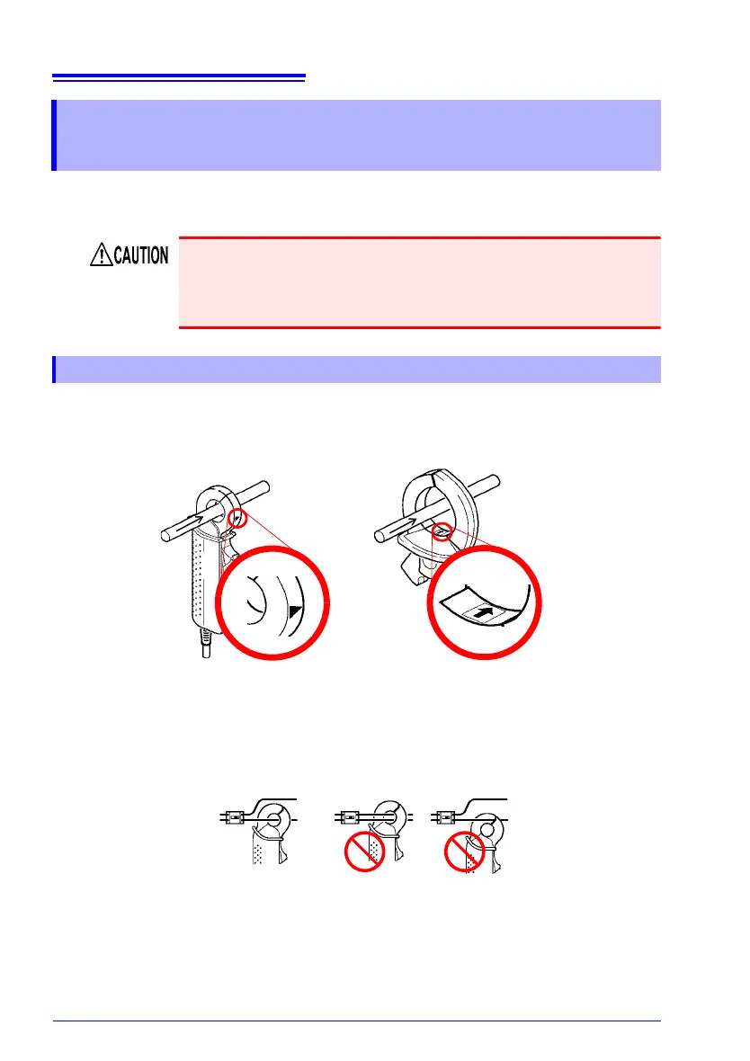
Make certain that the current flow direction arrow points toward the load.
Attach the clamp around only one conductor. Single-phase (2-wire) o
r three-phase
(3-wire) cables clamped together will not produce any reading.
3.6 Connecting Clamp Sensors to Lines to be
Measured
Note that the clamp sensor may be damaged if the applied current
exceeds the maximum input current.
For more information about clamp sensor specifications, see the
instruction ma
nual that came with the clamp sensor.
Load Current Measurement
Line
Load side
Source
side
Line
Load side
Current Flow
Direction Arrow
Source
side
Example
Model 9660 Clamp on Sensor Model 9661 Clamp on Sensor
Current Flow
Direction Arrow