3.5 Connecting the Voltage Cords to Lines to be Measured
51
3
Chapter 3 Connecting to Lines to be Measured
3
Connect the voltage cords to the lines to be measured while checking the [WIR,
DIAG] screen.
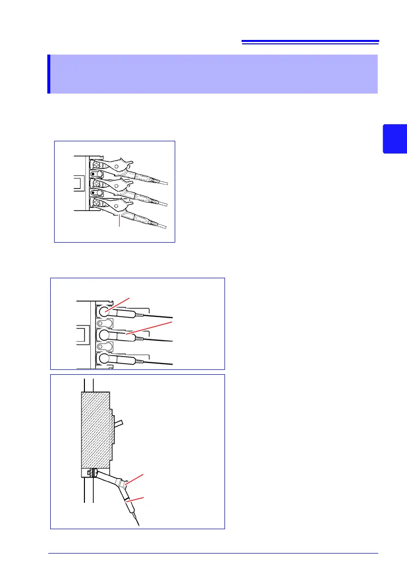
Example: When using the alligator clips
Example: When using Model 9804-01 or 98
04-02 Magnet Adapter
(optional, standard screw: M6 pan head screw)
3.5 Connecting the Voltage Cords to Lines to
be Measured
Secondary side of breaker
Model L9438-53 Voltage Cord
Securely clip the cords to the metallic part of the
screw or wiring bar on the secondary side of the cir-
cuit breaker.
Secondary side
of breaker
Model 9804-01/9804-02
Magnet Adapter
Model
L9438-53
Voltage Cord
Connect the magnetic part of the 9804-
01 or 9804-02 tip to the screws on the
secondary side of the breaker.
Secondary side of breaker
Model 9804-01/9804-02
Magnet Adapter
Model L9438-53
Voltage Cord
The weight of the voltage cords may
prevent you from making a perpen-
dicular connection to the Model
9804-01 or 9804-02 Magnet Adapter.
In this case, connect each cords so
that it is hanging off the adapter in a
manner that balances its weight.
Check the voltage values to verify
that the connections have been
made securely.