3.2 Setting Measurement Conditions on the Wiring Diagram Screen
43
3
Chapter 3 Connecting to Lines to be Measured
3
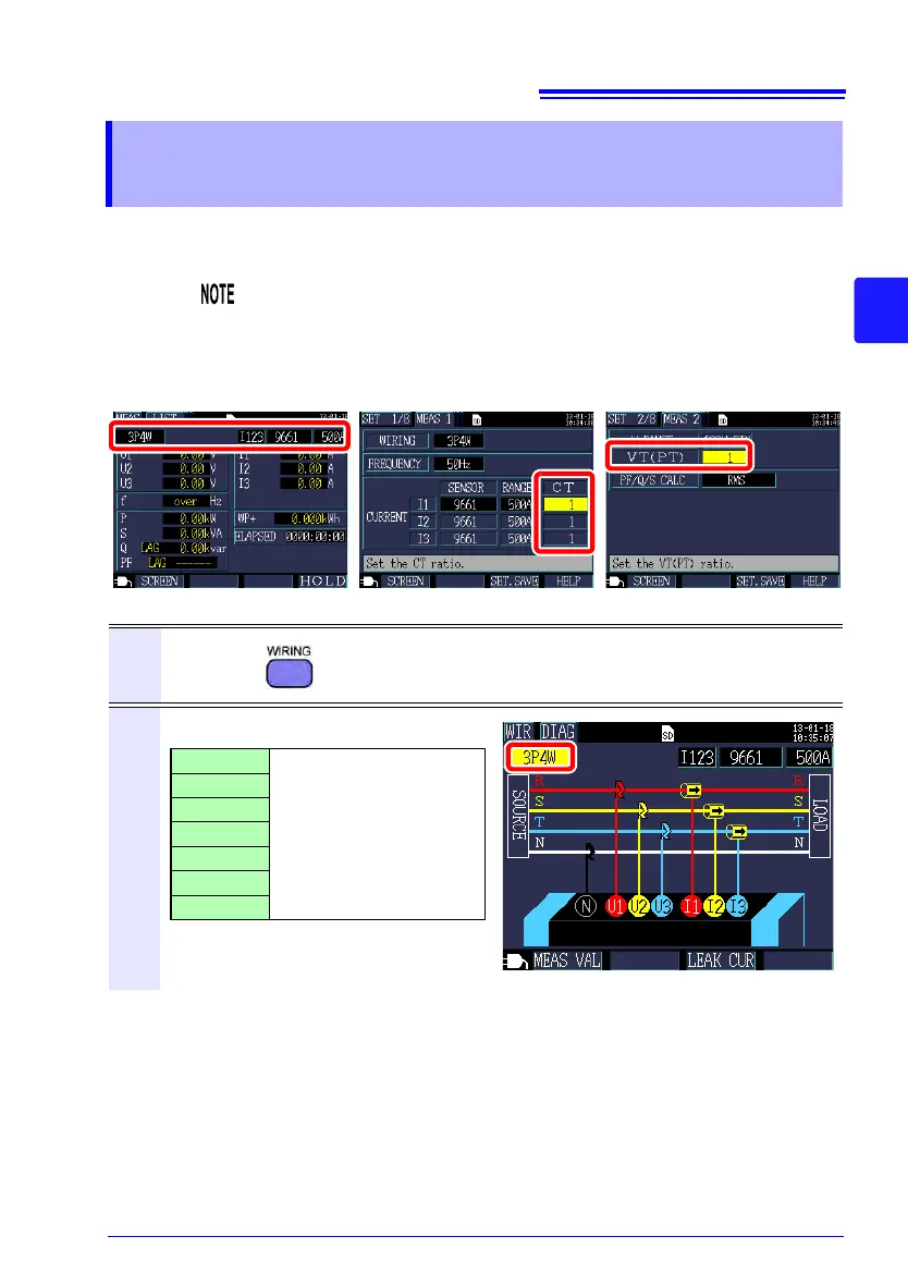
Use the following procedure to display the [WIR, DIAG] screen and
set the wiring method and clamp sensor being used.
3.2 Setting Measurement Conditions on the
Wiring Diagram Screen
The wiring method, clamp sensor, and current range settings can
be configured on the Measurement screen, Settings screen, or
Wirings screen. The CT ratio and VT (PT) ratio settings, if
needed, can be configured on the Settings screen.
See: 4.2, "Changing Measurement Settings" (p. 63)
[SET 1/8, MEAS 1] screen [SET 2/8, MEAS 2] screen[MEAS, LIST] screen
1
Press the key to display the [WIR, DIAG] screen.
2
Select the wiring method.
1P2W
For more detailed set-
tings, see the table on
the following page.
1P3W
1P3W1U
3P3W2M
3P3W3M
3P4W
I only