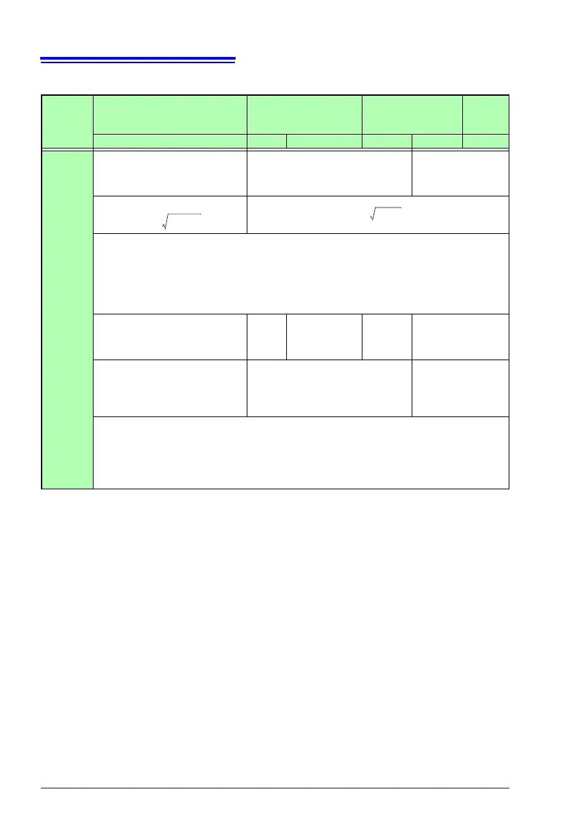
12.5 Calculation Formulas
202
* Subscript c: measurement channel
Reactive power
Wiring
setting
Item
Single-phase
2 wire
Single-phase
3 wire
Three-phase
3 wire
Three-
phase
4 wire
1P2W 1P3W 1P3W1U 3P3W2M 3P3W3M 3P4W
Reactive
power
Q [v
ar]
Q
1
Q
1
Q
2
Q
1
Q
2
Q
3
PF/Q/S (RMS calculation)
Q
c
=si
Q=si
• When S < |P| due to the effects of measurement error, unbalance, or other factors, S = |P| and
Q = 0.
• The component si indicates lag and lead. The sign of reactive power Q (fundamental wave
reacti
ve power
) is used.
Positive sign: Lag [Display indicates LAG
,
and output data is positive.]
Negative sign: Lead [Display indicates LEA
D, and output data is negative.]
Q
1
Q
1
Q
2
Q
1
Q
2
=U
1(1)r
×I
2(1)i
-U
1(1)i
×I
2(1)r
Q
1
Q
2
Q
1
Q
2
Q
3
PF/Q/S (fundamental wave calcu-
lation)
Q
c
=-U
c(1)r
×I
c(1)i
+U
c(1)i
×I
c(1)r
Q = Q
1
+Q
2
Q = Q
1
+Q
2
+Q
3
• This reactive power Q is defined as the fundamental wave reactive power.
• (1): Harmonic calculation fundamental wave (1st order)
• r: Post-FFT resistance component; i: post-FFT reactance component
• Positive sign: Lag [Display indicates LAG
,
and output data is positive.]
Negative sign: Lead [Display indicates LEA
D, and output data is negative.]