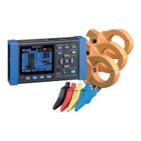
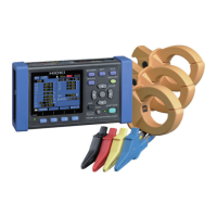
3.8 Verifying Correct Wiring (Wiring Check)
58
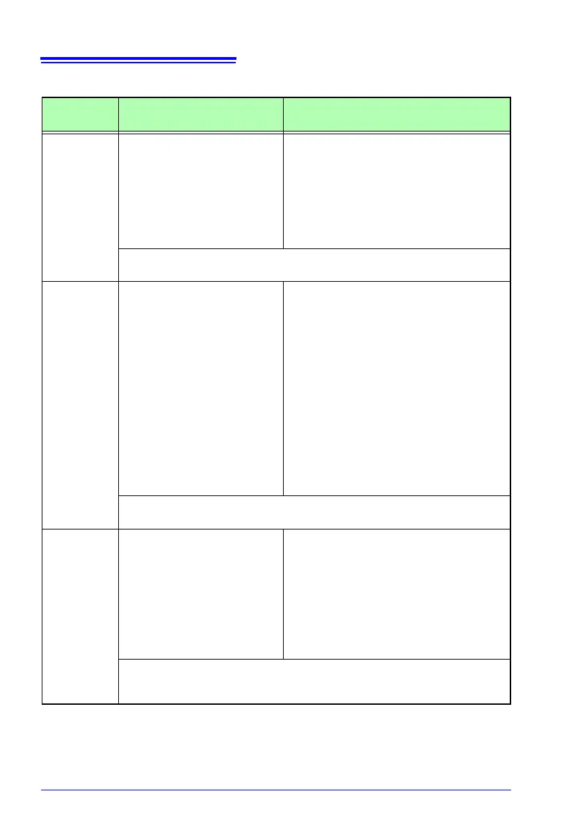
If the wiring confirmation result is [CHECK] or [FAIL]
wiring confir-
mation item
Judgment conditions Confirmation steps
Voltage
input
FAIL will display when volt-
age value is less than 50V.
FAIL will display when at
wiring other than 1P2W
, the
lowest voltage value is 70%
or less of the highest volt-
age value.
• Are the voltage test leads completely
inserted into the voltage input terminals?
• Are the alligator clips attached to the volt-
age test leads properly?
• Are the alligator clips completely
at
t
ached to the metallic part of the objects
to be measured?
See: 3.3, "Connecting the Voltage Cords" (p. 47)
See: 3.5, "Connecting the Voltage Cords to Lines to be Measured" (p. 51)
Current
input
FAIL will display when input
is less tha
n
1% of the cur-
rent range.
CHECK will display when
input is
less
than 10% of the
current range.
When no current is flowing, a Wiring
Check cannot be
performed. Operate
the equipment and keep current flowing
in order to check the wiring.
If the equipment cannot be operated,
a proper Wiring Check cannot be con-
ducted. Visually check for proper wiring
before me
asuring.
• Are the clamp-on sensors properly
inserted into the current input terminals?
• Are the clamp-on sensors clamped cor-
rectly?
• Is the set current range too large for the
inp
u
t level?
See: 3.4, "Connecting a Clamp Sensors" (p. 49)
See: 3.6, "Connecting Clamp Sensors to Lines to be Measured" (p. 52)
Voltage
phase
FAIL will display when the
volt
age p
hase exceeds the
range (±10 degrees of refer-
ence.)
• Are the wiring settings correct?
• Are the voltage leads correctly wired?
• Were the phases incorrectly laid out dur-
ing construction? Switch the voltage test
lea
ds and adjust the connections of the
clamp-on sensors so that PASS is dis-
played. To double-check, use a phase
de
tector to confirm that the phases are in
the correct sequence.
See: 3.2, "Setting Measurement Conditions on the Wiring Diagram Screen" (p.
43)
See: 3.5, "Connecting the Voltage Cords to Lines to be Measured" (p. 51)