4.2 Changing Measurement Settings
64
Clamp sensor, Current range
Selects the clamp sensor being used and the current range.
See: 3.2, "Setting Measurement Conditions on the Wiring
Diagram Screen" (p. 43)
CT ratio
Set when using an external CT.
• When a factory reset (p. 81) is performed to reset the instrument
to its default settings, no measurem
ent line frequency will have
been set. When you turn on the instrument, first set the fre-
quency to the measurement line frequency.
See: "Setting the Language and Measurement Line Frequency
(50/60 Hz)" (p. 28)
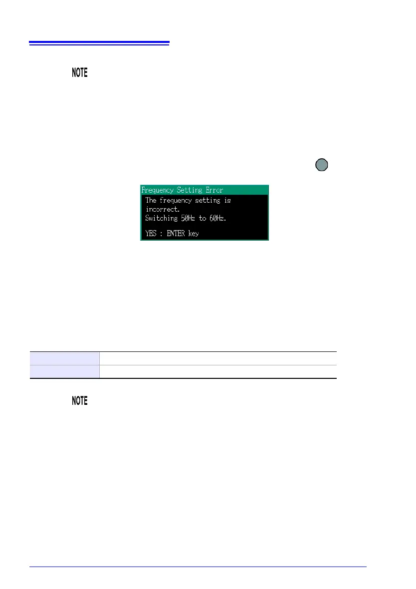
• The [Frequency Setting Error] dialo
g
box will be displayed if
the instrument detects voltage input and determines that the fre-
quency differs from the set frequency. Press the [ENTER]
key and change the frequency settings.
Selection
Manual 0.01 to 9999.99
Select 1/40/60/80/120/160/200/240/300/400/600/800/1200
• When taking measurements on the secondary side of a current
transformer (CT), you can set the CT ratio in order to convert the
readings to their primary-side equivalents and display the
results. For a CT with a primary-side current of 200 A and a sec
-
ondary-side current of 5 A, the CT ratio would be
40 (200 A / 5
A).
• If the 5 A current range were selected with the current sensor, it
would
be multiplied by the CT ratio of 40 to yield a current range
of 200 A.