4.8 Viewing Motor Measurement Values (Model PW3390-03 only)
102
If the [Harm sync src] is set to [Ext] when pulses are input to CH B for the rotation signal, voltage and
current phase shift based on the pulses can be seen.
Measuring Electrical Angle with Multiple Pulses
• Use of the original signal (Z phase) is recommended. The original (Z phase) signal serves as a refer-
ence pulse for consistent phase measurements.
• When multiple pulses are used as the rotation signal input without the original (Z phase) signal, the ref-
erence pulse is determined upon synchronization, so upon resynchronization after sync unlock occurs,
a different pulse may become the reference standard.
4.8.2 Measuring Motor Electrical Angle
• Harmonic analysis by synchronization with the rotation signal input pulse requires that the
pulse count be an integer multiple of the input frequency. For example, a 4-pole motor
requires a pulse count that is an integer multiple of two, and a 6-pole motor requires a pulse
count that is an integer multiple of three.
• When a motor with internal wiring is measured as a 3P3W3M wiring system, the voltage and
current phase angles can be measured using the
-Y transform function.
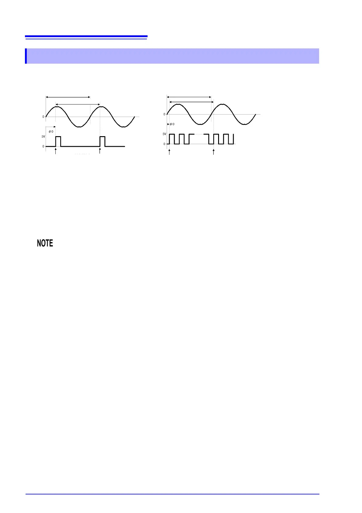
Single Pulses Multiple Pulses
Fundamental Frequency(U1)
Calculation Range
Calculation Range
Fundamental Frequency(U1)
External Sync Signal
External Sync Signal
Reference
Reference Reference Reference
Phase difference