4.2 Viewing Power Measurements, and Changing the Measurement Configuration
49
4
Chapter 4 Viewing Measurement Values
When viewing power measurements, [Power], [Voltage], and [Current] are displayed so that measured
values can be confirmed. Press to display the Measurement screen, and select the desired [CH]
page with the keys. Power measurements can be displayed in a list, and detailed voltage
and current values can be displayed.
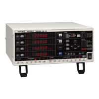
Press . (The screen shows values for Wiring mode 1, four 1P2W systems.)
4.2 Viewing Power Measurements, and
Changing the Measurement Configura-
tion
4.2.1 Displaying Power Measurements
Displaying Power
RMS Voltage
RMS Current
Power Factor
Active Power
Apparent Power
Reactive Power
Power Phase Angle
Frequency
• Average rectified RMS converted value is displayed for Urms or Irms according to the
rectification setting.
See "4.2.5 Selecting the Rectification Method" (p. 60)
• Polarity of power factor (), Reactive power (Q), and power phase angle () shows
the LEAD or LAG. "No polarity sign" means "LAG" and "-" means "LEAD".
• The polarity of power factor, reactive power and power phase angle may not be sta-
ble when the voltage and current has big level difference or power phase angle is
around zero.
• During 3P3W2M measurement, the active power (P), reactive power (Q), apparent
power (S), power factor (
), and power phase angle () for each channel indicate
intermediate measurement results. Use the total values (P12, P34, etc.) for final eval-
uation purposes.

 Loading...