Redundancy
152
8.3
Redundant coupling
RM Web L3P
Release
4.1
03/08
– Port: on
– Automatic configuration (autonegotiation):
on for twisted-pair connections
– Manual configuration: 100 Mbit/s FDX
for glass fiber connections
Note: If VLANS are configured, note the VLAN configuration of the
coupling and partner coupling ports.
In the Network/Ring Coupling configuration, select for the coupling and
partner coupling ports
– VLAN ID 1 and “Ingress Filtering” disabled in the port table and
– VLAN membership U in the static VLAN table.
Note: Operating the redundancy manager and two-Switch coupling func-
tions at the same time runs the risk of creating a loop.
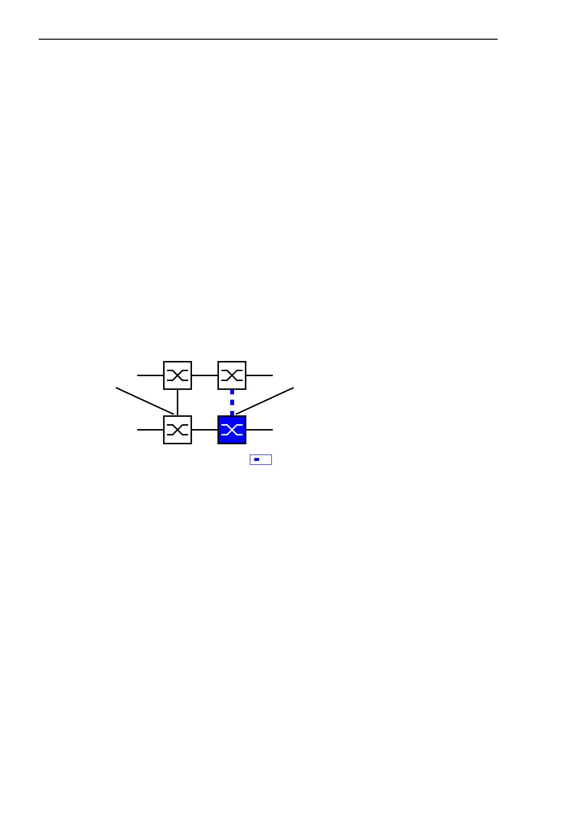
Select two-Switch redundant coupling (see fig. 54).
Figure 54: Two-Switch coupling
The following settings apply to the Switch displayed in blue in the selected
graphic.
Select the coupling port (see fig. 53), (see table 31).
With “Coupling port” you specify at which port you are connecting the
network segments.
If the STANDBY DIP switch is ON, connect the main line to the
coupling port.
Note: Configure the coupling port and the HIPER-Ring ports on different
ports.
Activate the function in the “Operation” frame (see fig. 53).
The displays in the “Select port” frame mean (see fig. 53):
– “Port mode”: The port is either active or in stand-by mode.
IO
STAND-BY
Coupling
port
Partner
coupling
port
 Loading...