Redundancy
160
8.3
Redundant coupling
RM Web L3P
Release
4.1
03/08
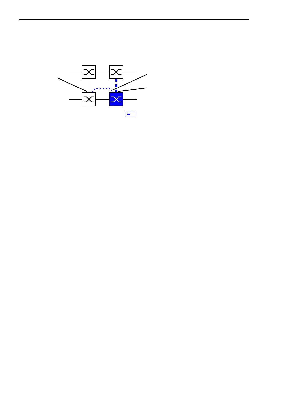
Select two-Switch redundant coupling
with control line (see fig. 60).
Figure 60: Two-Switch coupling with control line
The following settings apply to the Switch displayed in blue in the selected
graphic.
Select the coupling port (see fig. 59), (see table 32).
With “Coupling port” you specify at which port you are connecting the
network segments.
If the STANDBY DIP switch is ON, connect the main line to the
coupling port.
Select the control port (see fig. 59), (see table 32).
With “Control port” you specify at which port you are connecting the
control line.
Note: Configure the coupling port and the HIPER-Ring ports on different
ports.
Activate the function in the “Operation” frame (see fig. 59).
You now connect the redundant line and the control line.
The displays in the “Select port” frame mean (see fig. 59):
– “Port mode”: The port is either active or in stand-by mode.
– “Port state”: The port is either connected or not connected.
– “IP Address”: The IP address of the partner, if the partner is already
operating in the network.
The displays in the “Information” frame mean (see fig. 59):
– “Redundancy guaranteed”: One of the lines affected can fail, as a
redundant line will then take over the function of the failed line.
– “Configuration failure”: The function is incomplete or incorrectly
configured.
Coupling port
Partner
coupling
port
Control port
IO
STAND-BY
 Loading...