4 Electrical wiring
139
4
SMGB0077 rev.0 - 01/2013
4.1.6 Electrical connection of RPI units
Work prior to the electrical connection
1 Turn off the power supply switches before starting work and t the appropriate locks and safety warnings.
2 Wait 5 minutes after turning off the power supply switches.
3 Check that the fans on the indoor and outdoor units are at a standstill before starting work.
N O T E
• Theelectricalpowerfortheunitmustinvolveaspecicpowerline,withanexclusivepowercontrolswitchand
residual current breaker, installed in line with local or national safety regulations.
• Check that the electrical power line has enough capacity to supply the unit. Its length, the cable diameter and
their protection (sleeve or jacket) must be appropriate for the unit.
• For further information, always consider the current regulations in the country where the unit is to be installed.
C A U T I O N
• Riskofre:cablesmustnevertouchtherefrigerantpipes,printedcircuitboards(PCB),sharpedgesorelec-
trical components inside the unit to avoid damaging them.
• Loose connection terminals may lead to cable and terminal overheating. The unit may operate incorrectly,
leadingtoariskofre.Checkthatthecablesarermlysecuredtotheconnectionterminals.
Electrical connection
Check that the power supply for the RPI indoor unit is 230 V. If not, replace connectors CN on the TF transformers in the
electrical box.
N O T E
The service panel for the indoor unit fan motor is at the bottom of the unit and the electrical box service panel is
on the right-hand side.
Open the service panel.
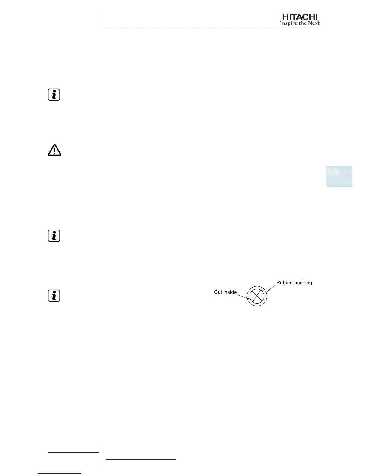
Cut the centre of the rubber bushing in the wiring connection hole.
N O T E
• To prevent the screws from falling from the terminal box,
do not remove them completely, hold onto the terminal
and check that the screw is secure through the hole in the
terminal.
• Use the following screws for the terminal box:
- M4 screw for the power supply.
- M3.5 screw for the operating line.
 Loading...


