10 Servicing
372
SMGB0077 rev.0 - 01/2013
(2 portions)
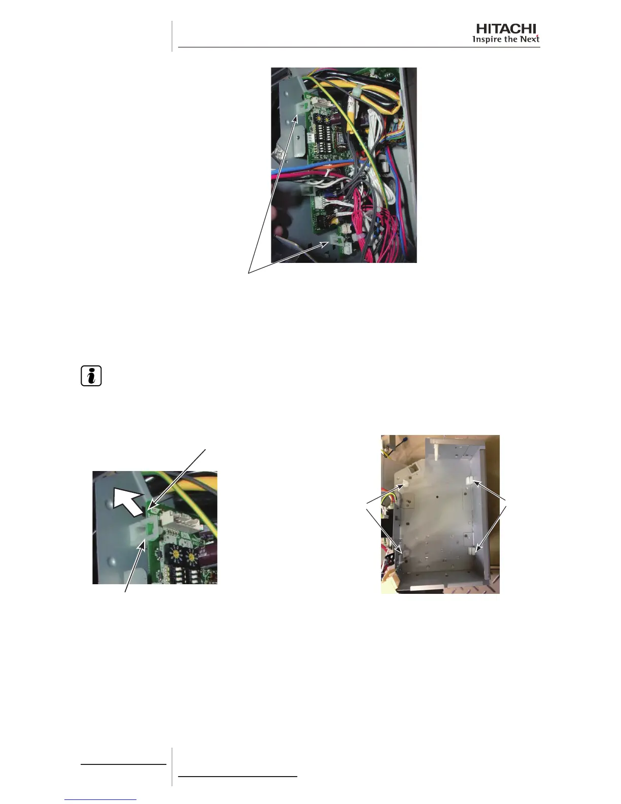
Specers on Front Side
g. Insert the new PCB1 for replacement into the grooves of two (2) spacers on the rear side. Then attach the PCB1
to the hooks on the front side to x it.
h. Connect the connectors to the PCB1 and attach the xing plate for the terminal board, the electrical box stay, the
electrical box cover and the terminal board cover in the reverse procedure.
N O T E
• Make sure that the wirings will not get caught and that all the connectors will be connected correctly.
• If the unit with the expansion valve kit is used, regard “expansion valve coil” as “expansion valve relay cord.”
the direction of the arrow
to undo the hooks.
Spacers on Front Side
Spacers on
Front Side
(2 Portions)
Spacers on
Rear Side
(2 Portions)
10.9.7 Removing Electrical Box
For RPK-(0.8-1.5)FSN(H)3M
1 Remove the front panel according to the “Removing Front Panel” chapter
2 Remove 1 screw xing the terminal board cover to remove it. Also remove 1 screw xing the electrical box cover to
remove it.
3 Then, remove the power source wiring, the transition wiring and the wiring for the remote control switch from the
terminal board.
4 Remove the connectors (on the PCB1) for the freeze protection thermistor, gas pipe thermistor, inlet air thermistor,
outlet thermistor, auto-louver, fan motor and expansion valve coil, and the earth wire.
 Loading...


