10 Servicing
320
SMGB0077 rev.0 - 01/2013
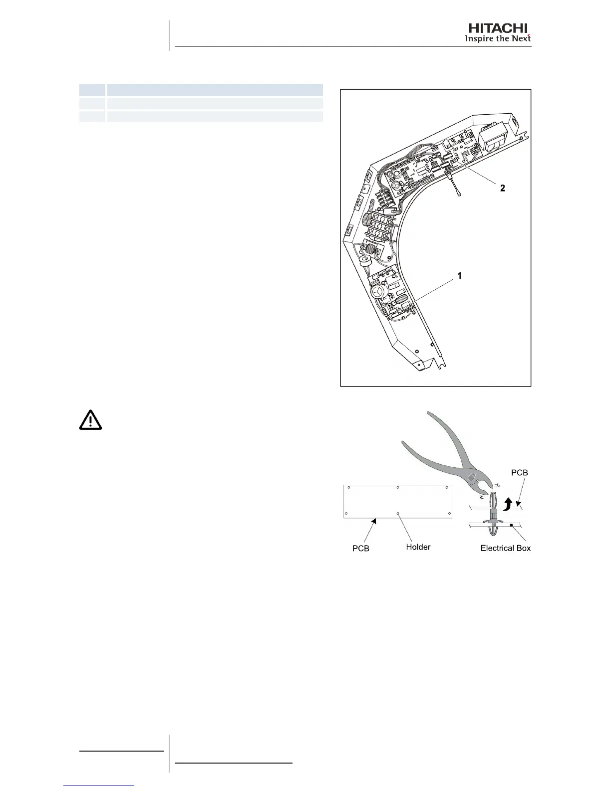
10.2.7 Removal of the printed circuit board (PCB)
Nº Part
1 Power supply PCB
2 Control PCB
Remove the air inlet grille as indicated in chapter Removal of the
air inlet grille.
Remove the electrical box cover as indicated in chapter Removal
of the electrical box cover.
Separate all of the wiring connectors on the printed circuit boards
(PCB).
Remove the PCB by pressing carefully on the support tabs with
long-tipped pliers, as shown in the gure.
C A U T I O N
• Do not touch the electrical components of the PCB.
• Do not apply force to the PCB, as this could damage it.
• Pay special attention to the position of the connectors
on the PCB. An incorrect position during installation may
damage the PCB.
 Loading...


