7 Test run
247
7
SMGB0077 rev.0 - 01/2013
6 Check the indication on the remote control:
Indication on the remote
control
Unit status Fault
Inspection points after swit-
ching off the power supply
The on/off LED ickers (once a
second), along with the unit no.
and alarm code 03.
The unit does not start.
The operating line connection
wires are incorrect or loose.
a. Connection order of
each terminal board.
The fuse on the PCB is
likely to have been disa-
bled during a incorrect
wiring. The fuse can
only be recovered once
using the DSW on the
PCB. Go to point 7.
b. Adjustment of the
screws on each terminal
board.
c. Connection order of the
power supply cables
between the indoor and
outdoor units.
The on/off LED ickers (once
every 2 seconds).
The unit does not start.
The remote control cable con-
nection is incorrect.
As in point 3 A, B and C
The ickering display is diffe-
rent to that indicated above.
The unit does not start. The unit
starts and then stops.
The thermistor connection
or that of other connectors is
incorrect. The trip switch is
triggered.
Use the alarm code table in the
service manual to check this
(service personnel are respon-
sible for this check).
The on/off LED ickers (once
every sec.). And the unit num-
ber 00, the alarm code dd and
unit code E.00 icker.
The unit does not start.
The remote control cable con-
nection between the indoor
units is correct
See the fault table in the tech-
nical catalogue (this must be
performed by technical per-
sonnel).
Go back to point 1 after the check.
7 Instructions for recovery when the transmission circuit fuse is disabled
a. Correct the terminal board wiring.
b. Enable the 1st pin on DSW7 of the indoor unit PCB.
7.2.2 PC-ARF remote control
(1) Turn ON the power supply for all the indoor units.
(2) For the models with the auto-address function, wait for 3 minutes approximately. The addressing is automatically
performed. (There is a case that 5 minutes is required according to the setting condition.) After that, select using
language from “Menu”. Refer to the operation manual for details.
(3) Press and hold “
” (menu) and “ ” (return) simultaneously for at least 3 seconds.
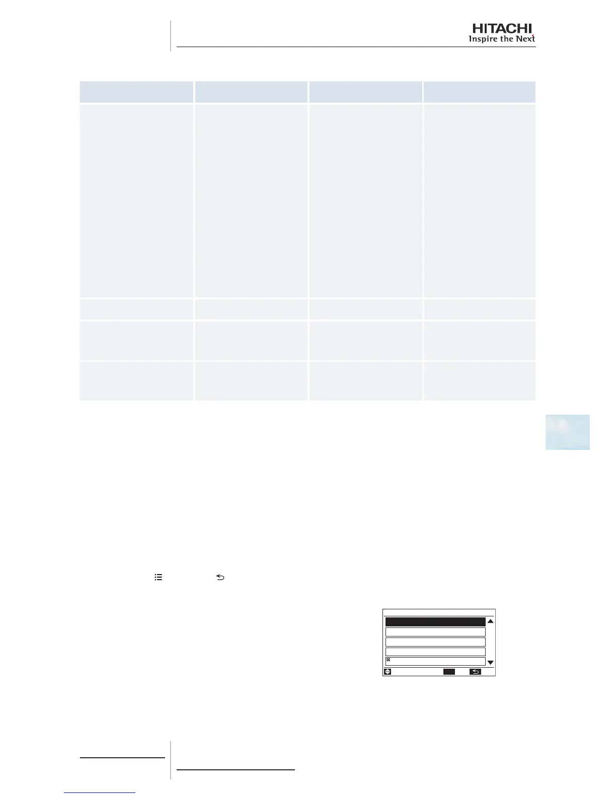
Test run screen
a.
The test run menu will be displayed.
ADJ
/
OK
Test Run Menu
Test Run
Function Selection
Thermistor Selection
Input/Output
Function 5
01
03
ENT. RTN.SEL.
 Loading...


