5 Control system
191
5
SMGB0077 rev.0 - 01/2013
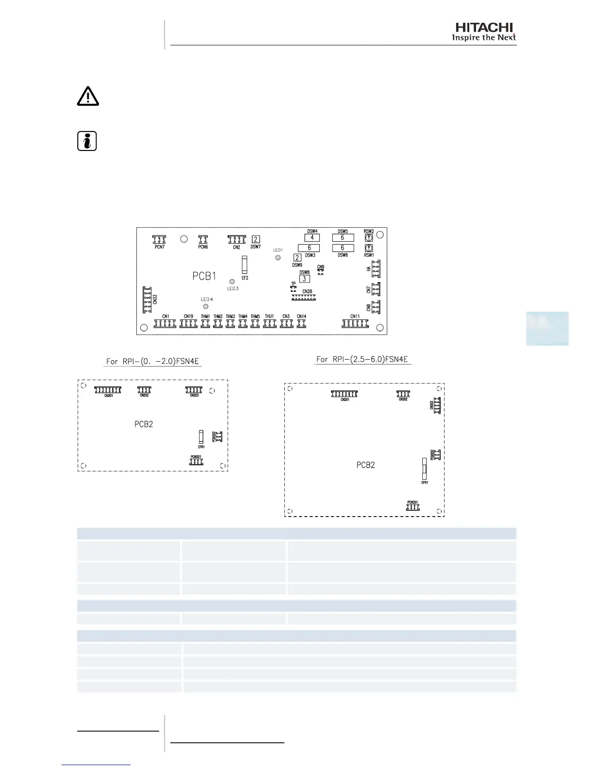
5.1.6 Printed circuit board for RPI(M)-(0.8-6.0)FSN4E
C A U T I O N
Turn off the power supply before setting the DIP switches. If not, the settings will not be valid.
N O T E
• Thesymbol“■”indicatesthepositionoftheDIPswitches.Theguresshowthesettingbeforetransmission
or after selection.
• Ifthe“■”markisnotdisplayed,thisindicatesthatthepositionofthepinisnotaffected.
The indoor unit PCB operates with four types of DIP switches, a slide switch and a rotary switch. The position is as follows:
8
PCB1 LED indicator
LED1 Red
This LED indicates the transmission status between the indoor unit
and the remote control.
LED3 Yellow
This LED indicates the transmission status between the indoor unit
and the outdoor unit.
LED4 Red PCB power supply
PCB2 LED indicator
LED1 Yellow PCB power supply
Connector indication
PCN6 Drain pump
PCN7 Printed circuit board 2
PCN201 Terminal board
PCN202 Printed circuit board 1
 Loading...


