10 Servicing
356
SMGB0077 rev.0 - 01/2013
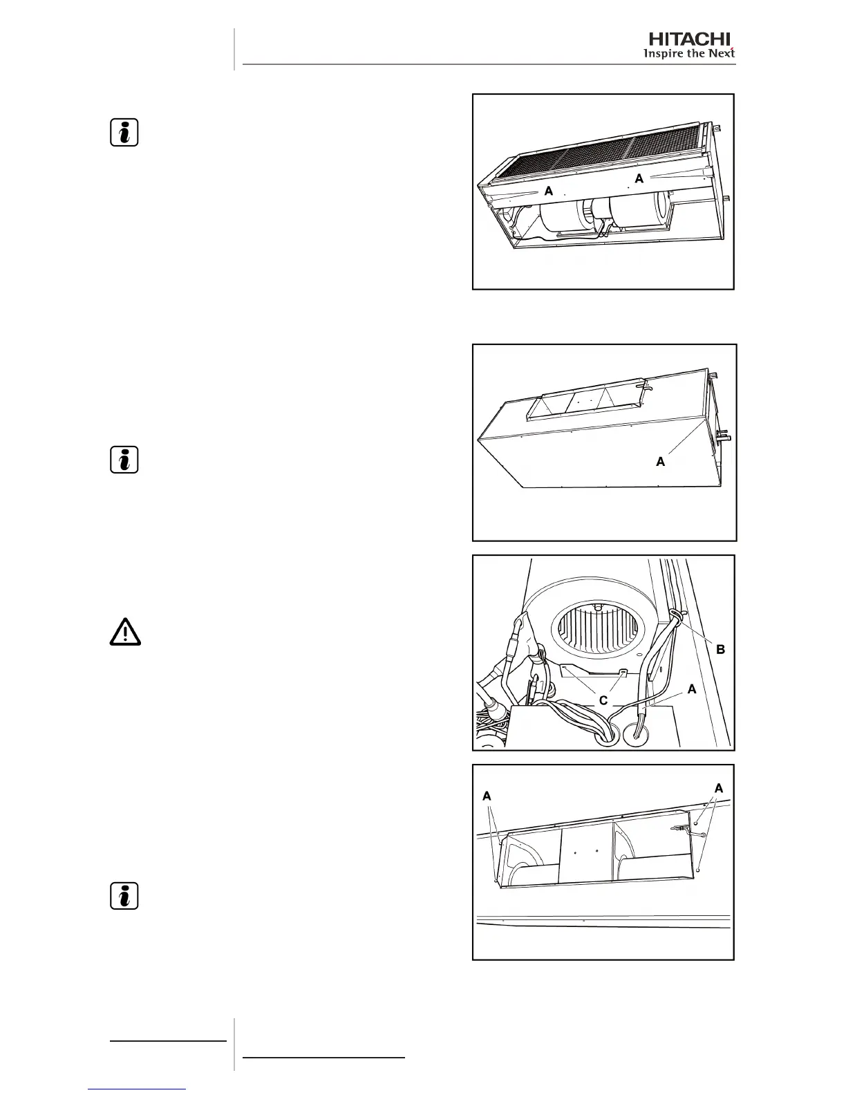
Remove the screws -A- securing the drain pan and remove it.
N O T E
Whentting,sealthedrainhosegasketcorrectly.
10.7.6 Fan removal
Remove all screws -A- from the lower cover of the unit and
separate it.
Remove the electrical box cover Removal of the electrical box
cover.
Disconnect the fan motor.
N O T E
To disconnect and remove the fan motor, previously see the
chapter corresponding to the wiring diagrams in this Manual.
Remove the drain pan Removal of the drain pan.
Remove the wiring A- from the electrical box and release it from
the support -B-.
Remove the screws -C- on both sides of the fan.
C A U T I O N
• Make sure the fan can be removed correctly, without the
risk of injuring anyone in the surrounding area.
• The fan is heavy. Request the assistance of two operators
to hold the fan while it is being removed.
Remove the screws -A- on both sides of the fan and remove the
unit.
When tting, connect the fan motor connector to the electrical box
in line with the previous conguration:
• Connector CN24 LSP (Low Static Pressure); (factory-supplied).
• Connector CN25 HSP (High Static Pressure).
N O T E
Service cover fan assembly parts (runner, fan casing, fan
motor) must be performed once the fan assembly has been
removed from the unit.
 Loading...


