5 Control system
185
5
SMGB0077 rev.0 - 01/2013
Connector indication
CN36 Motor for drain discharge mechanism
EFR1 PCB1 fuse
EFS1 PCB1 fuse
HA Not used
Switch indication
DSW3 Capacity code
DSW4 Unit model code
DSW5, RSW2 Refrigerant cycle number
DWS6, RSW1 Indoor unit number settings
DSW7 Fuse re-establishing
DSW9 Not used
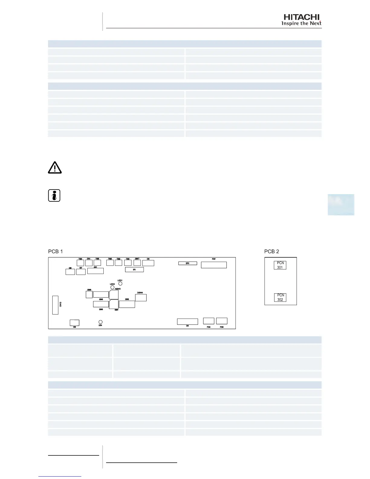
5.1.2 Printed circuit boards for RCI-(1.0-6.0)FSN3Ei
C A U T I O N
Turn off the power supply before setting the DIP switches. If not, the settings will not be valid.
N O T E
• Thesymbol“■”indicatesthepositionoftheDIPswitches.Theguresshowthesettingbeforetransmission
or after selection.
• Ifthe■markisnotdisplayed,thisindicatesthatthepositionofthepinisnotaffected.
The indoor unit PCB operates with ve types of DIP switches and two rotary switches. The position is as follows:
LED indicator
LED1 Red
This LED indicates the transmission status between the indoor unit
and the remote control.
LED3 Yellow
This LED indicates the transmission status between the indoor unit
and the outdoor unit.
LED4 Red PCB power supply
Connector indication
PCN4 Not used
PCN6 Drain pump
PCN7 Printed circuit board 2
PCN301 Terminal board
PCN302 Printed circuit board 1
THM1 Air inlet thermistor
 Loading...


