5 Control system
194
SMGB0077 rev.0 - 01/2013
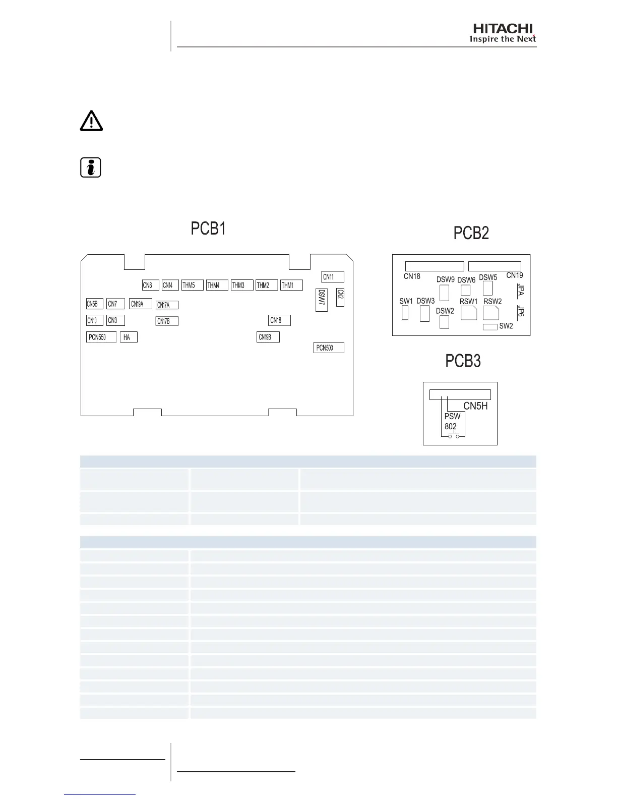
5.1.8 Printed circuit board for RPK-FSN(H)3M units
For RPK-(0.8-1.5)FSN(H)3M
C A U T I O N
Turn off the power supply before setting the DIP switches. If not, the settings will not be valid.
N O T E
• Thesymbol“■”indicatesthepositionoftheDIPswitches.Theguresshowthesettingbeforetransmission
or after selection.
• Ifthe■markisnotdisplayed,thisindicatesthatthepositionofthepinisnotaffected.
LED indicator
LED1 Red
This LED indicates the transmission status between the indoor unit
and the remote control.
LED3 Yellow
This LED indicates the transmission status between the indoor unit
and the outdoor unit.
LED4 Green PCB power supply
Connector indication
PCN500 Terminal board 1
PCN550 Motor for indoor fan
THM1 Air inlet thermistor
THM2 Air outlet thermistor
THM3 Freeze protection thermistor
THM4 Not used
THM5 Gas piping thermistor
CN2 Terminal board 2
CN3 Not used
CN5A Printed circuit board 3
CN5B Not used
CN7 Not used
CN8 Not used
 Loading...


