10 Servicing
351
10
SMGB0077 rev.0 - 01/2013
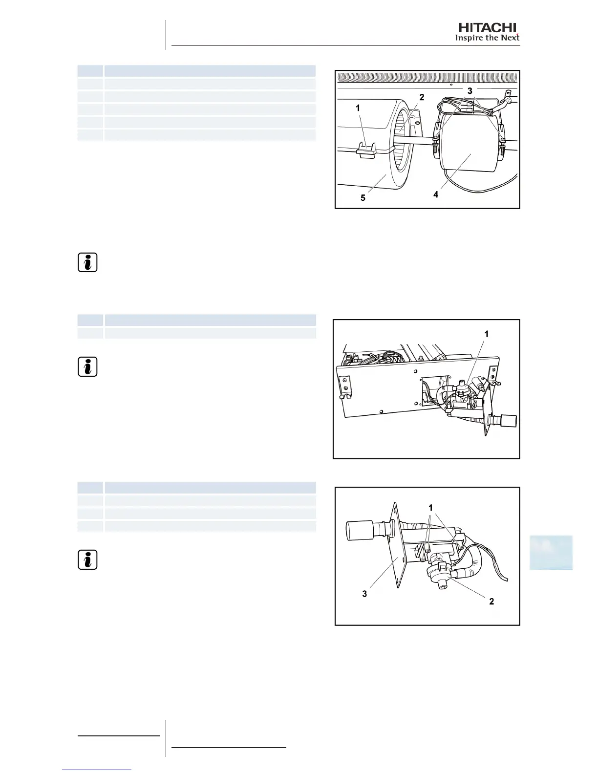
Nº Part
1 Locks
2 Duct
3 Fixture supports
4 Fan motor
5 Fan casing
Remove the rear cover as indicated in chapter Removal of the inlet
and outlet air thermistor.
Remove the tape located in the centre of the casing.
Press the locks and remove half of the fan casing.
Remove the xture support screws and carefully remove the motor together with the fans.
Loosen the screws securing the fans to the motor shaft.
N O T E
Ifthefancasingistobefullyremoved,removethescrewssecuringtheotherhalftothefanmotorxture.
10.6.5 Removal of the drain mechanism
Nº Part
1 Drain pump
N O T E
To disconnect and remove the drain mechanism, previously
see the chapter corresponding to the wiring diagrams in this
Manual.
Remove the drain pump support screws and remove it.
Nº Part
1 Bolts
2 Drain pump
3 Service cover
N O T E
Prior to installing the new pump:
1 Remove the electrical box from the unit to connect it to
the printed circuit board (PCB) in line with the instructions
given in chapter Removal of the electrical box.
2 Seal the drain hose gaskets correctly.
 Loading...


