10 Servicing
371
10
SMGB0077 rev.0 - 01/2013
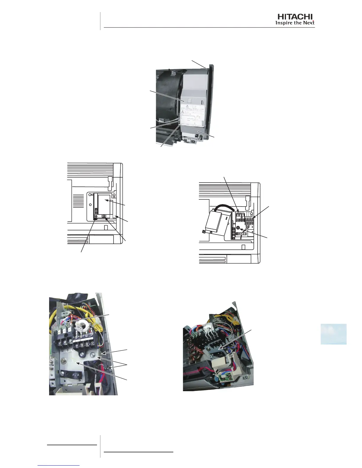
b. Remove 1 screw (A) xing the terminal board cover to remove it. Then, remove 2 screws (C) xing the electrical
box cover to remove it.
(B)-2: Screw for Electrical Box Cover
Power Source (TB1)
Screw for
Earth Wiring
Terminal Board for
Remote Control Switch
Cable and Transmission
(TB2)
A B 1
c. Remove 2 screws for the electrical box stay to remove it.
d. Remove 1 screw for the xing plate for the terminal board and tilt the board frontward.
Screw for Fixing Plate
for Terminal Board
Screw for
Electrical Box Stay
Electrical Box Stay
Fixing Plate for
Terminal Board
Fixing Plate for
Terminal Board
e. Remove the connectors (on the PCB1) for the freeze protection thermistor, gas pipe thermistor, inlet air thermistor,
outlet air thermistor, transmission, remote control switch, power source, external input/output, auto-louver, PCB for
indication, fan motor, PCB for receiver and expansion valve coil.
f. Undo the hook of the spacers (2 portions) on the front side. Then remove the PCB1 from the electrical box.
 Loading...


