10 Servicing
386
SMGB0077 rev.0 - 01/2013
N O T E
Take care not to twist the piping.
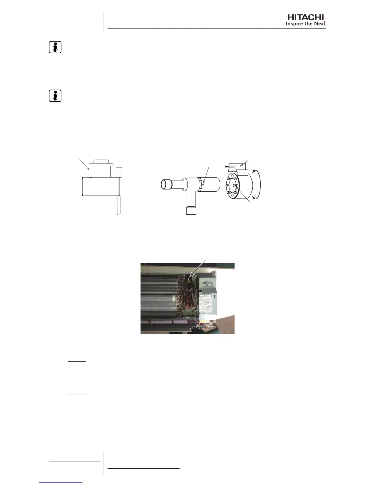
3 Insert the new expansion valve coil for replacement into the expansion valve body. Fit the projection portions into the
detents with the wiring outlet facing up.
N O T E
• The detents are located 90º apart in a circle and the projections are located 180º apart in a circle.
• Fit the projection portions into the detents. If inserting the coil incorrectly, it may cause malfunction of the expansion
valve coil.
4 After the work, clamp the wirings for the expansion valve, the freeze protection thermistor, gas pipe thermistor and inlet
air thermistor with one (1) plastic band.
30±5 mm
Valve Coil for Replacement
Detent of Electronic
Expansion Valve Coil
Rotation Direction
Expansion Valve Coil
(A)
Projection Portion
on Valve Body
For RPK-(2.0-4.0)FSN(H)3M
(1) The rear pipe for the heat exchanger, the electronic expansion valve, and the piping at the inlet/outlet
of the electronic expansion valve are protected with butyl sheets. Remove butyl sheets covering the
piping, the expansion valve coil and the expansion valve body .
Electronic Expansion Valve Coil
(2) Rotate the expansion valve coil in the direction of the arrow (A) shown in the gure below. After
releasing the detents for the expansion valve coil from the projection portions of the expansion valve
body, pull up the coil to remove it.
NOTE:
Take care not to twist the piping.
(3) Insert the new expansion valve coil for replacement into the expansion valve body. Fit the projection
portions into the detents with the wiring outlet facing down.
NOTE:
The detents are located 90
o
apart in a circle and the projections are located 180
o
apart in a circle.
Fit the projection portions into the detents. If inserting the coil incorrectly, it may cause malfunction of
the expansion valve coil.
(4) After the work, protect the expansion valve coil with butyl sheets and mount the heat exchanger in
the reverse procedure.
 Loading...


