ACUIX High Speed Dome User Manual
Document 800-01023 Rev A 21
02/08
2
Switch Settings
The ACUIX has two DIP switches (SW5 and SW6) on the pan and tilt printed circuit board
(PCB) for setting the protocol, baud rate, and parity. These settings must match the
control equipment settings.
There are four rotary switches (SW1, SW2, SW3, and SW4) for setting the ACUIX logical
address for control purposes.
A DIP switch can also be used to restore the default settings and another DIP switch to
override the switch settings for the logical address.
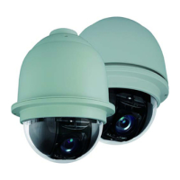
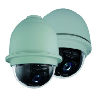
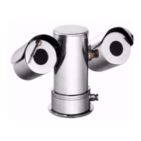
Figure 2-1 ACUIX Pan and Tilt Camera Assembly
Figure 2-2 Location of DIP and Rotary Switches on Main Board
Printed circuit board
DIP switches
SW5 and SW6
Rotary switches
SW1, SW2,
SW3, & SW4
 Loading...