IFP-300 / IFP-300ECS Manual P/N LS10145-001SK-E:B 12/18/2017 144
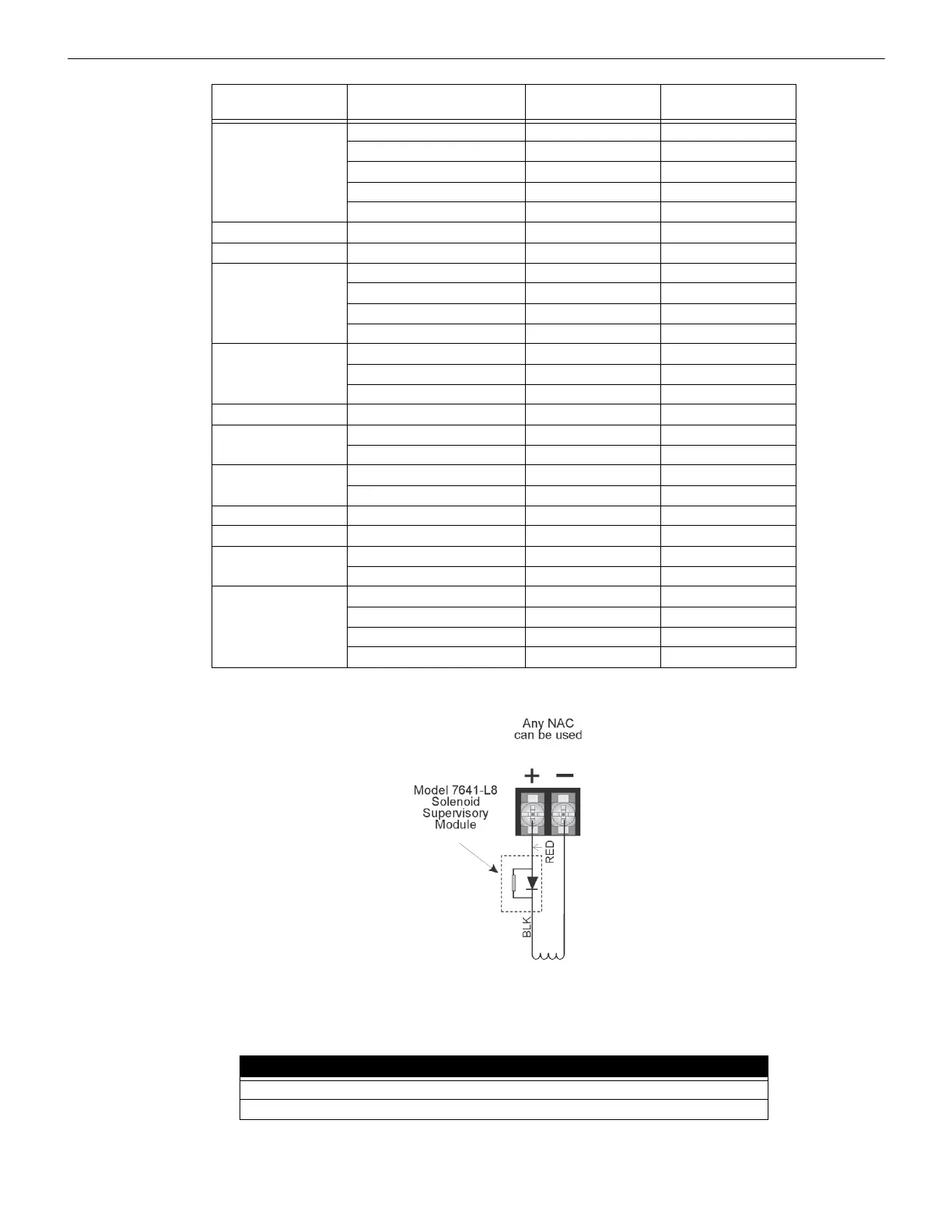
Figure 10.6 Wiring Configuration for Solenoid
10.7.1 Single Interlock Zone Releasing
A single interlock zone utilizes a minimum of two addressable detectors and a designated manual release switch.
Manufacturer Part Number Rated Voltage, DC
Rated Current,
Milliamp
Asco T8210A107 24 VDC 700
8210G207 24 VDC 442
HV2740607 24 VDC 375
HV2838521 24 VDC 375
HV2740608 24 VDC 375
Honeywell/Skinner 701X7028 24 VDC 917
Barnbrook System EA45 24 VDC 200
Kidde Fenwal 890181 24 VDC 2000
486500 24 VDC 290
895630 24 VDC 2000
897494 24 VDC 1500
Minimax 88 7363 24 VDC 1040
88 5738 24 VDC 1040
88 9323 24 VDC 500
Nohmi Bosai R85M10 24 VDC 1200
Parker Hannifin 70610006 24 VDC 417
10610707 24 VDC 417
Snap-tite 2823A-2NB-A4F6 24 VDC 458
2823A-2NB-A4F5 12 VDC 917
TLX PA0036-A 24 VDC 600
Versa Valves CGS-4232-NB3-S2 24 VDC 438
Victaulic 753E 24 VDC 364
767 24 VDC 364
Viking 11591 24 VDC 417
11595 24 VDC 417
11592NC 24 VDC 416
16360 24VDC 500
Table 10.3 Approved Releasing Solenoids
Important!
Only addressable detectors can be used. No conventional detectors can be used.
Each Single Interlock Zone input requires at least one manual release switch.

 Loading...


