45 IFP-300 / IFP-300ECS Manual P/N LS10145-001SK-E:B 12/18/2017
4.11.2 5880 Connection to Panel
The 5880 connects to the panel via the SBUS. Make connections as shown in Figure 4.34. After the 5880 is connected to the panel, it
must be added to the system. This programming step is described in Section 4.13.
Figure 4.34 5880 Connection to Main Control Panel Assembly
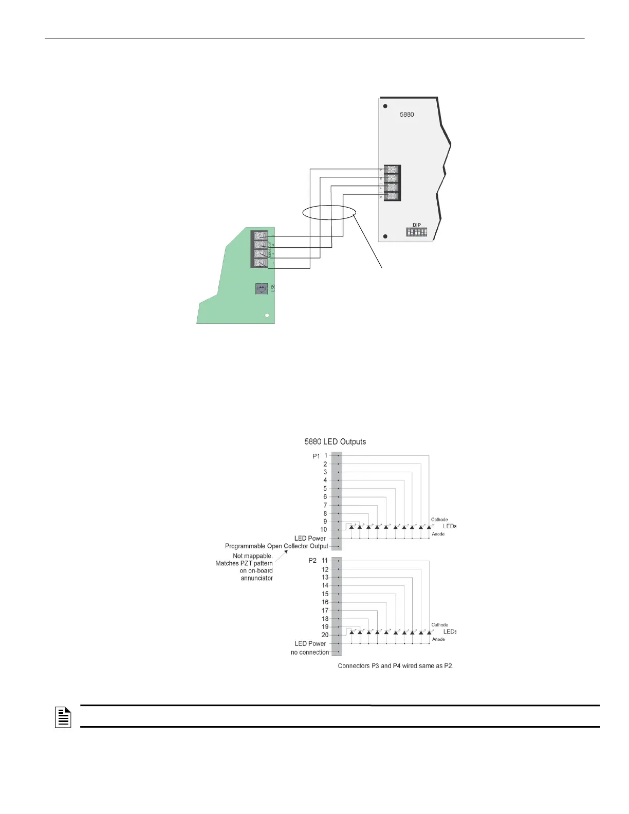
4.11.3 LED Wiring
There are four 12-pin connectors on the 5880 board for connecting LEDs. Each LED gets its power from Pin 11. Internal resistors are
sized so that there is approximately 10 mA of current for each LED, no series resistors are required. LED outputs can be mapped to out-
put circuits. See Section 9 for programming details.
Wire the LEDs as shown in Figure 4.35.
On connector P1, Pin 12 is a common open collector output for controlling a PZT. If used, the 5880 PZT will match the PZT pattern of
the on-board or remote annunciator.
Figure 4.35 5880 Board Layout
NOTE: The circuit connected to common “Open Collector Output” (last pin on P1) must be current limited so that no more than 100 mA of
current is allowed to flow into the open collector transistor

 Loading...


