IFP-300 / IFP-300ECS Manual P/N LS10145-001SK-E:B 12/18/2017 12
3.6 Board Assembly Diagram
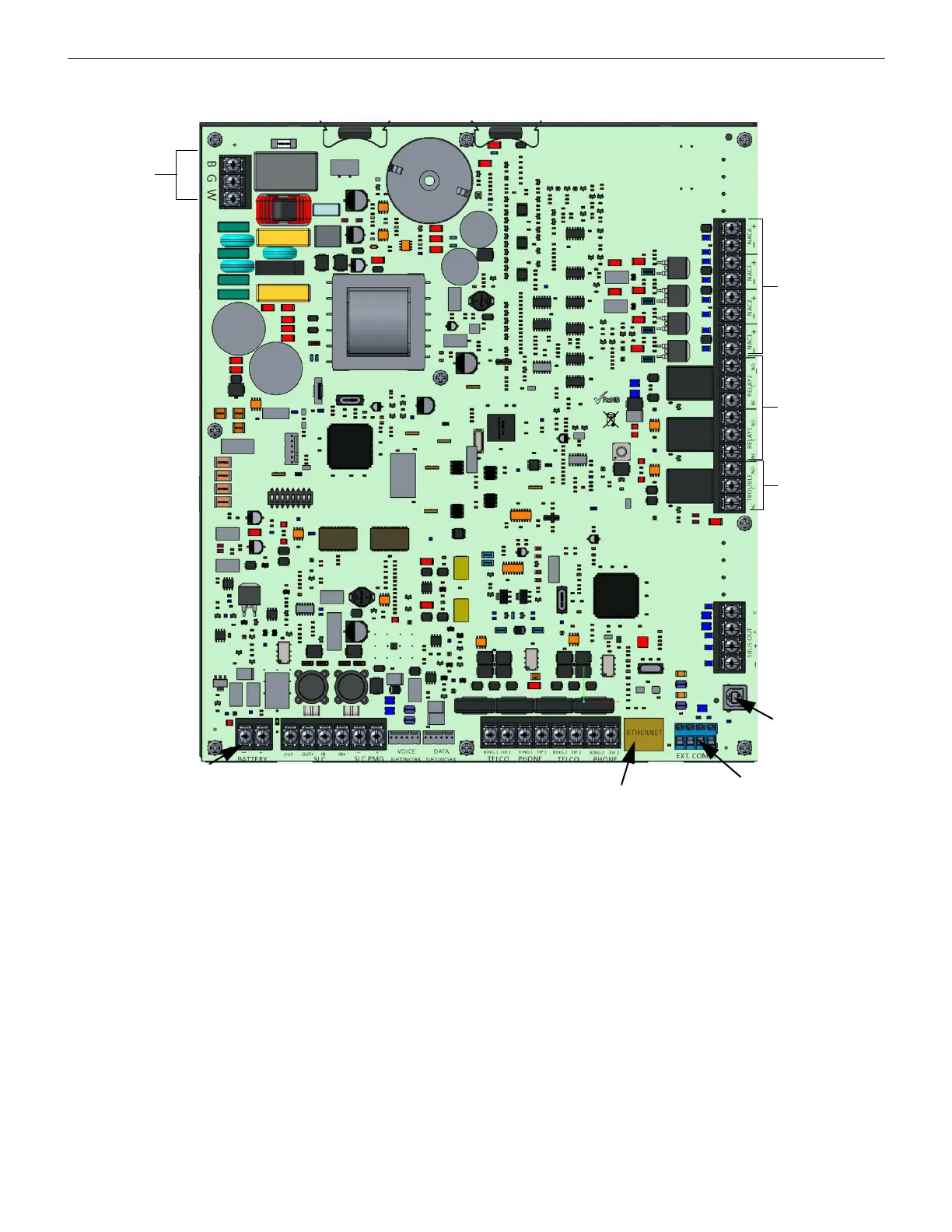
Figure 3.3 Model IFP-300 Assembly
Figure 3.3 shows the circuit board that attaches the IFP-300 assembly to the cabinet. If you should need to remove the board assembly
for repair, remove the nine mounting screws (six on the main circuit board and 3 on the heat-sink) which hold the assembly in the cabi-
net. Then lift the entire assembly out of the cabinet.
3.7 Calculating Current Draw and Standby Battery
This section is for helping you determine the current draw and standby battery needs if you are using IDP addressable devices
(Table 3.2) or SD addressable devices (Table 3.4).
3.7.1 Current Draw Worksheet Requirements
The following steps must be taken when determining IFP-300 current draw and standby battery requirements.
1. Use the Current Draw Worksheet to determine current draw and standby battery requirements. Use Table 3.2 if installing IDP SLC
Devices, Table 3.3 if installing SK SLC Devices and Table 3.4 if installing SD SLC Devices, to determine current draw. For the
IFP-300, the worst case current draw is listed for the panel, addressable devices, and all SBUS expanders. Fill in the number of
addressable devices that will be used in the system and compute the current draw requirements for alarm and standby. Record this
information in the Current Draw Worksheet on Line A.
2. Add up the current draw for all auxiliary devices and record in the table at Line B.
3. Add up all notification appliance loads and record in the table at Line C.
NAC / Aux
Power
Form C
Relays
Phone lines
SLC
AC Power
Input
SBUS Out
Connections
Battery
Connections
Form C
Trouble
Relay
SLC
PGM
Circuits
EXT COMM
Ethernet
USB

 Loading...


