13 IFP-300 / IFP-300ECS Manual P/N LS10145-001SK-E:B 12/18/2017
4. For notification appliance circuits and auxiliary devices not mentioned in the manual, refer to the device manual for the current
ratings.
5. Make sure that the total alarm current you calculated, including current for the panel itself, does not exceed 6.0 A. This is the
maximum alarm current for the IFP-300 control panel. If the current is above 6.0 A you will need to use a notification power
expander(s) such as the Honeywell 5496 NAC Expander, to distribute the power loads so that the IFP-300 or the power expanders
do not exceed their power rating. Refer to the current draw worksheets provided with the 5496 manual so you do not exceed their
power requirements.
6. Alternatively, you may network additional IFP-300ECS’ to get additional power.
7. Complete the remaining instructions in the appropriate Current Draw Worksheet for determining battery size requirements.
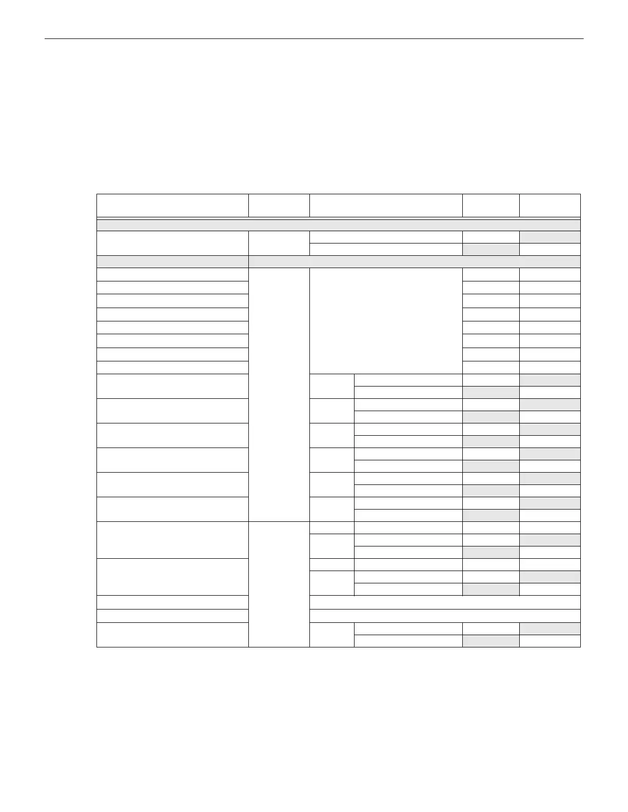
3.7.2 Current Draw Worksheet for IDP SLC Devices
Use Table 3.2 to determine current requirements during alarm/battery standby operation when IDP SLC devices are installed. The IFP-
300 FACP supports up to a total of 300 SLC devices, consisting of any combination of Sensors and Modules.
7
Device
Number of
Devices
Current per Device
Standby
Current
Alarm
Current
For each device use this formula: This column X This column = Current per number of devices.
Fire Panel (Current draw from battery)
1 Standby: 190 mA 190 mA
Alarm: 250 mA 250 mA
Addressable SLC Detectors
IDP-Photo
Standby/Alarm: .30 mA
1
mA mA
IDP-Photo-T
mA mA
IDP-PhotoR
mA mA
IDP-Ion
mA mA
IDP-Heat
mA mA
IDP-Heat-HT
mA mA
IDP-Acclimate
mA mA
IDP-Heat-ROR
IDP-Photo-W/IV
SLC Standby: 200mA mA
Alarm: 4.5mA mA
IDP-PHOTO-R-W/IV
SLC Standby: 200mA mA
Alarm: 4.5mA mA
IDP-PHOTO-T-W/IV
SLC Standby: 200mA mA
Alarm: 4.5mA mA
IDP-HEAT-W/IV
SLC Standby: 200mA mA
Alarm: 4.5mA mA
IDP-HEAT-ROR-W/IV
SLC Standby: 200mA mA
Alarm: 4.5mA mA
IDP-HEAT-HT-W/IV
SLC Standby: 200mA mA
Alarm: 4.5mA mA
IDP-Beam (without integral test)
SLC Standby/Alarm: 2 mA mA mA
Aux. Pwr Standby: 2 mA mA
Alarm: 8.5 mA mA
IDP-Beam-T (with integral test)
2
SLC Standby/Alarm: 2 mA mA mA
Aux. Pwr Standby: 2 mA mA
Alarm: 8.5 mA mA
DNR
3
(non-Relay)
None, included with IDP-PhotoR
DNR
4
(with Relay)
None, included with IDP-PhotoR & IDP-Relay
IDP-FIRE-CO
SLC Standby: 30 mA mA
Alarm: 7.2 mA mA
Table 3.2 Current Draw Worksheet for IDP SLC Devices

 Loading...


