IFP-300 / IFP-300ECS Manual P/N LS10145-001SK-E:B 12/18/2017 22
1. Total does not include isolator devices or accessory bases.
2. If using 24 VDC aux power only. No standby or alarm current for battery calculation if using 24 VAC, 120 VAC or 240 VAC.
3. If using door holders, you do not need to consider door holder current for alarm/battery standby, because power is removed during
that time. However, during normal operation, door holders draw current and must be included in the 6.0A total current that can be
drawn from the panel.
4. Use next size battery with capacity greater than required.
5. The FACP can only support 2 devices w/LED’s on. This current draw has been added to the panels alarm current.
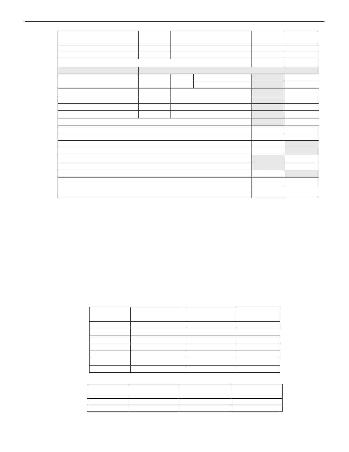
3.7.5 Maximum Battery Standby Load
Table 3.5 and Table 3.6 show the standby load calculations for the IFP-300 based on 24 and 90 hours of standby. The standby load calcu-
lations of line D in the Current Draw Calculation Worksheet must be less than the number shown in Table 3.5 and Table 3.6 for the
selected battery size, standby hour and alarm time. The numbers below have a built in 20% de-rating factor for the battery amp-hour
capacity
Alarm/Standby: mA
mA mA
Alarm/Standby: mA
mA mA
B
Auxiliary Devices Current
Notification Appliance Circuits Refer to devices manual for current rating.
5495/5499 Power Supply 24 VDC One input circuit: 15 mA
mA
Both input circuits: 30 mA
mA
Alarm: mA
mA
Alarm: mA
mA
Alarm: mA
mA
Alarm: mA
mA
C
Notification Appliances Current
mA
D
Total current ratings of all devices in system (line A + line B + C)
mA mA
E
Total current ratings converted to amperes (line D x .001):
AA
F
Number of standby hours (24 or 60 for NFPA 72, chapter 1, 1-5.2.5):
H
G
Multiply lines E and F. Total standby AH
AH
H
Alarm sounding period in hours. (For example, 5 minutes =.0833 hours)
H
I
Multiply lines E and H. Total alarm AH
AH
J
Add lines G and I.
4
AH
Multiply by the Derating Factor
x 1.25
Total ampere hours
required
Device
Number of
Devices
Current per Device
Standby
Current
Alarm
Current
Table 3.4 Current Draw worksheet for SD Devices
Rechargeable
Battery Size
24 hr Standby,
5 mins. Alarm
24 hr Standby,
15 min alarm
24 hr Standby,
20 min alarm
17AH 535mA 473mA 442mA
18AH 569mA 506mA 475mA
24AH 769 mA 706mA 675mA
33AH 1.07A 1.01A 975mA
35AH 1.14A 1.07A 1.04A
40AH 1.30A 1.24A 1.21A
55AH 1.80A 1.74A 1.71A
Table 3.5 :Maximum Battery Standby Loads for 24 Hour Standby
Rechargeable
Battery Size
90 hr Standby,
5 min alarm
90 hr Standby,
15 min alarm
90 hr Standby,
20 min alarm
33 AH N/A N/A N/A
40 AH 347mA 331mA 322mA
Table 3.6 Maximum Battery Standby Loads for 90 Hour Standby*

 Loading...


