25 IFP-300 / IFP-300ECS Manual P/N LS10145-001SK-E:B 12/18/2017
Section 4: Control Panel Installation
4.1 Mounting the Control Panel Cabinet
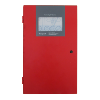
The IFP-300 cabinet can be surface or flush mounted. Cabinet base dimensions are 24.75"H x 14.5" W x 3.91"D. If you flush mount the
cabinet, there should be 1.5" to 1.75" of cabinet extruding from the wall, this should be measured from either the top edge or bottom
edge to the exterior side of the sheet rock. Do NOT flush mount in a wall designated as a fire break.
The IFP-300ECS cabinet can be surface or flush mounted. Cabinet base dimensions are 26.5"H x 20"W x 4.1"D If you flush mount the
cabinet, there should be 1.5" to 1.75" of cabinet extruding from the wall, this should be measured from either the top edge or bottom
edge to the exterior side of the sheet rock. Do NOT flush mount in a wall designated as a fire break.
Figure 4.1 FACP Cabinet Base
4.1.1 Preventing Water Damage
Water damage to the fire system can be caused by moisture entering the cabinet through the conduits. Conduits that are installed to enter
the top of the cabinet are most likely to cause water problems. Installers should take reasonable precautions to prevent water from enter-
ing the cabinet. Water damage is not covered under warranty.
4.1.2 Removing the IFP-300/ECS Assembly from the Housing
If it should ever be necessary to remove the control panel assembly from the cabinet for repair, do so by removing the screws that hold
the control panel in to the cabinet. Do not attempt to disassemble the circuit boards.
4.1.3 Ethernet Connection
Ethernet connection is used for IP communication. For port location see Figure 3.3.
4.2 AC Connection
At installation, connect the AC terminals to the power source as shown in Figure 4.2. It may be necessary for a professional electrician to
make this connection.
IFP-300
IFP-300ECS
20"
26.5"
14.5"
24¾"
11"
16"
WARNING: RISK OF ELECRICAL SHOCK AND EQUIPMENT DAMAGE
SEVERAL DIFFERENT SOURCES OF POWER CAN BE CONNECTED TO THIS PANEL. DISCONNECT ALL SOURCES OF
POWER BEFORE SERVICING. THE PANEL AND ASSOCIATED EQUIPMENT MAY BE DAMAGED BY REMOVING AND/OR
INSERTING CARDS, MODULES OR INTERCONNECTING CABLES WHILE THIS UNIT IS ENERGIZED

 Loading...


