51 IFP-300 / IFP-300ECS Manual P/N LS10145-001SK-E:B 12/18/2017
2. Configure the circuit through programming (see Section 9.6).
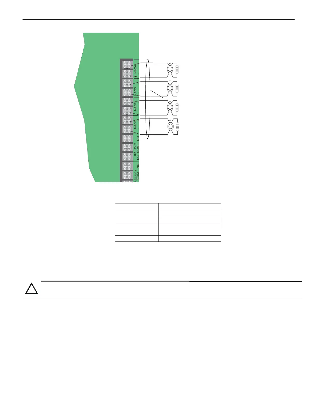
Figure 4.43 Class B Notification Appliance Circuit Wiring
Maximum voltage drop is 3V per Class A circuit. See Table 4.4.
Class A Notification Wiring
You must use an appliance from the list of compatible appliances in Appendix A.
To install a Class A notification appliance circuit:
1. Wire the Class A notification appliances as shown in Figure 4.44.
Current Maximum Impedance
1.0A 3
1.5A 2
2.0A 1.5
2.5A 1.2
3.0A 1.0
Table 4.4 Maximum Impedance Class A
Alarm Polarity Shown
4.7 kEOL
Supervised
Power Limited
Notification Wiring
Max. Impedance: 1.5
All Circuits are Synchronized (Regulated). Rated at
27.4 VDC @ 3A Max.
CAUTION:
For proper system supervision do not use looped wire under terminals marked + and – of the Flexput connectors. Break wire runs to provide
supervision of connections.

 Loading...


