9Ć12 Product History and Service Notes
C3187Ć90000
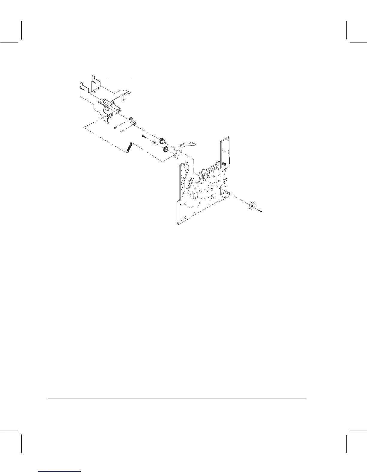
Engaging lever
EngagingĆlever spring
Screw
(Remove from inside)
Left sideplate
YĆtensioner bracket
CamĆgear support
Auto cam
IMPORTANT: You need a scissors as well as the tools listed in chapter 6.
1. Remove the window assembly and the left endĆcover.
2. Remove the the bail assembly, the encoder strip and the service station.
3. Remove the primer assembly.
4. Remove the YĆtensioner bracket and related assemblies.
5. Using scissors or a cutter, cut the teflon washers.
6. Using needleĆnose pliers, remove the teflon washers.
IMPORTANT: Ensure that you have removed all the teflon washers and that you are not
leaving any fragment between the sideĆplate and the autoĆcam.
If you are not able to remove them, perform the following additional steps:
a. Disassemble the plotter to access the automatic bailĆlift mechanism following the
procedure described in chapter 6.
b. ReĆinstall the bailĆlift mechanism WITHOUT the teflon washers.
7. Place the camĆgear support into the slot on the NEW YĆtensioner bracket included in the
bailĆmechanism assembly.
8. Install the YĆtensioner bracket on the left sideplate. Tighten the two left screws and leave
the right one loose.